
|
WIYN Instrumentation / |
|
Investigators
Matthew Bershady - PI | Contents | ||||
| Description | Construction | Performance | |||
| Phase-In Schedule | First Light | Observing Information | |||
| Shared Use | Commissioning | Data Processing | |||
| |||||
 |
 |
This project was funded by NSF grants AST-9618849, AST-9970780,
and the UW Graduate School. The page in maintained under NSF AST-0307417
and AST-0607516.
Figures and documents on this and related
web pages may not be reproduced or published without permission of the
Principal Investigators. |
| (i) | Installation | May 2001 |
| (ii) | Commissioning | May 2001 through Spring 2002 |
| (iii) | Shared-Use (See memo) | Fall 2001 - |
| (iv) | WIYN Institution-class Instrument | Fall 2002 - |
| (v) | Facility-class Instrument | Fall 2003 - |
First, read this memo and be sure that you agree with the terms.
If you do, contact the Instrument PI (Matt Bershady, mab@astro.wisc.edu, 608 265 3392) to reach an understanding and agreement on what science program SparsePak will be used.
Finally, email the appropriate letter of request listed below to the WIYN or KPNO Director well before your observations. Email the WIYN Director if you are a WIYN-consortium user. Email the KPNO Director if you are using NOAO time. It is important to cc a copy to the Instrument PI. When he receives this email he will send a similar letter to the appropriate Director, whereupon your SparsePak shared-use will be granted.
| Shared-Use Request Letter | WIYN-Institution Time | NOAO Time |
|
Science PI letter - you send this Instrument PI letter - I send this |
Science PI letter - you send this Instrument PI letter - I send this |
| Instructions: fill in blanks and email to jacoby@wiyn.org with cc to mab@astro.wisc.edu |
Instructions: fill in blanks and email to rgreen@noao.edu with cc to mab@astro.wisc.edu |
First Light: Night of May 6th, 2001. Tested were:
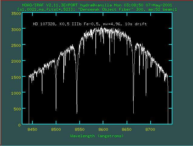 | HD 107328, K0.5 IIIb
Fe-0.5, mv=4.96, 10s drift (RV std) |
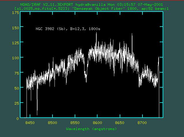 | NGC 3982, Sb, B=12,3, 1800s |
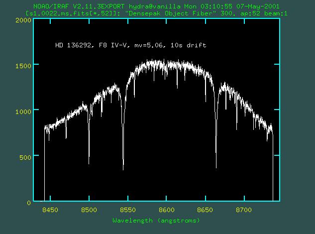 | HD 136292, F8 IV-V, mv=5.06, 10s drift (RV std) |
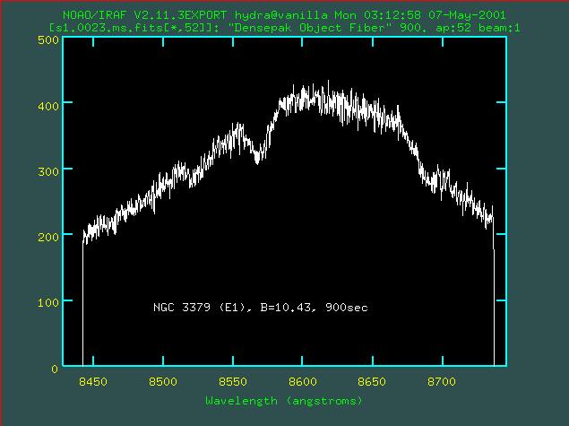 | NGC 3379, E1, B=10.4, 900s |
Here is an H-alpha velocity field of NGC 3982 from the second night, courtesy D. Andersen and M. Verheijen.
Commissioning run calibration and characterization are in the following two papers:
SparsePak: A Formatted Fiber Field-Unit for The WIYN Telescope Bench Spectrograph. II. On-Sky Performance, Bershady, M. A., Andersen, D. R., Verheijen, M. A. W., Westfall, K. B., Crawford, S. M., Swaters, R. A. 2005, ApJS, 156, 311 (reprint: [local pdf] [ApJS])
|
|
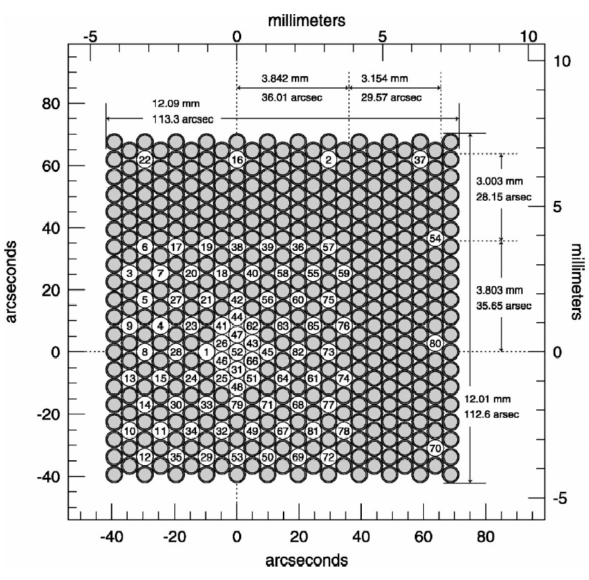
Array fill -- this 3-point pattern will fill in the aray in
the sparses 70x70 arcsec region.
|
Array sub-sample -- this 3-point pattern will sub-sample
the inner region of the array to increase spatial resolution.
|
||||||||||||||||||||||||
| Note - these offsets have been updated for the proper plate scale at the WIYN IAS f/6.3 focus of 9.374 arcsec/mm, and rounded off 0.1 arcsec precision. (See WIYN Facts). | |||||||||||||||||||||||||
How to make offsets: Between guided
exposures, small offsets should be
"unguided" for highest precision. This means turning off the
guiding, making the small move (or dither), moving the guide box
back onto the guide star, and finally "enabling" guiding with a
"zero lock." The last step ensures that the guider keeps the star
at the location within the guide box where it is placed,
i.e. it does not try and drag the star into the center of the box.
Spectrograph Setups & Calibration: At the present
time we have used SparsePak in three wavelength regimes in five orders
with the echelle grating (316@63.4), and 2nd-order at H-alpha for the
860 l/mm grating. Thanks are due to Di Harmer and Daryl Wilmarth for
carefully establishing the foci and optimum/comprimise camera-grating
distances!
The Bench Spectrograph echelle setup parameters, calibration exposure
times, and delivered spectral resolution are summarized below. For
the echelle, the camera-collimator angle is 11.0 degrees and the fiber
focus is -162 (-0.162 inches). For the 860@30.9 setup, the
camera-collimator angle is 30.0 degrees and the fiber focus is -212
(-0.212 inches). In all cases: the collimator focal length is 1021mm.
Exposure times are for un-binned data although 2x1 is often used for
MgI and CaII IRT setups (binning in spatial diretion). For these
cases, halve the exposure times. Exposure times for "ThAr" will change
until a new, permanent feed is established. As of Jan 2002, the "ThAr:
lamp is "CuAr."
Notes - (1) the spectrograph instrument setup parameters apply to any
fiber cable, as do the delivered performance in central wavelength and
dispersion. (2) Exposure times should scale with the relative fiber
area; spectral resolutions should be fairly constant because of the
large anamorphic demagnification. (3) The three "low" resolution
echelle setups have the same grating-camera distance. This means that
rapid switches can be made during the night by only changing filters
(alpha and camera focus too -- but from the GUI). (4) Order 7 setups
are problematic because of high grating angles. While these yield
incredibly high dispersions and large demagnification (hence high
resolution), they are difficult to focus over the full range in both
spatial and spectral dimensions. There is strong trade between spatial
and spectral foci. The high grating angles lead to substantial light
loss because these angles are both far off-blaze and so large the
grating does not fill the beam. We estimate that order 7 is down by
x2 at the 8600 central-wavelength setting and x3 at the 8750
central-wavelength setting compared to setups at the same central
wavelengths in order 6. (5) Dewar azimuth angle optimization was
tested for Jan 17 2002 run setups for order 6 and 7 centered at 8750.
Substantial improvements in uniformity of spatial focus was achieved.
Daryl Wilmarth suggests improvements could be made for other echelle
setting.
The easiest way to count the number of fibers is to run
noao.twodspec.apextract.apfind on a dome flat, as follows, with
these parameters:
Aperture "1" should be on the right side of the spatial profile in the
graphics window. It should be obvious from an immediate visual
inspection if there are indeed 82 fibers. Note that the vignetting for
the edge fibers should put their amplitude no lower than 50-60% of the
central, peak fibers.
Otherwise, counting fibers by hand is painful. If you must: Using an
"l" (spatial) cut in imexamine fiber 1 is at high pixel x values and
fiber 82 is at low pixel x values. Fiber 37 can be identified as the
anamalously low fiber found near the middle of the slit. If xstart=450
and xsize=100, cutting near the middle of the dispersion direction of
a dome flat (y = 1024) puts fibers 1, 2, and 3 at pixels (x) 159, 169,
and 180 respectively.
Bench Spectrograph Setups 860@30.9 316@63.4 (Echelle)
central wave (A)
6645
5131
6619
6625
6687 8605
8750 8652
8675
8750
order
2 (1.74)
11 (10.96)
9 (8.49)
8 (8.41)
7 (6.53)
6 (6.48)
alpha (degrees)
50.988
68.989
76.410
62.641
63.523 78.354
81.966 60.969
61.084
61.946
dewar azimuth
angle (degress) +0.100
-0.128
-0.128
-0.128
-0.128
+0.100 -0.128
-0.128
+0.100
grating-camera
distance (inches) 15.2
40.0
33.1
40.0
31.7
40.0
camera focus
(10-3 inches) -8
-19
-15 or
-16 for ends -17 or -16
+3
+2
+3
+8
blocking filter
(slot B: echelle)
(slot B: non-echelle) G5 (GG-495)
X14
X19
X19
X23
X23
full coverage (A)
927
262
253
411
294
573
central dispersion
(A/pix) 0.453
0.128
0.122
0.201
0.144
0.280
spectral FWHM (pix)
3.0
3.4
2.7
3.3
2.5
3.2
Spectral Resolution
(lambda/dlambda) 4877
11747
20318
10049
24003
9683
Wavelength calib:
(ThAr)
exposures (s) This has been changing because of
modifications of lamp feed.
Dome flats:
(High lamps)
exposures (s) 3
60
20
20
20
7
WARNING: We have found that some fibers (from as many as
1 to 5) appear to "snuff out" during the initial setup of the
spectrograph. THESE FIBERS ARE NOT BROKEN. The
cause is the filter blocking some number of edge fibers (at the top or
bottom of the SparsePak slit). This arises because the filter has been
inserted manually. Another sign that there is a problem is a marked
increase in scattered light as seen in a dome flat. A robust
solution is to remove and re-insert the filter via the GUI.
Do this as a matter of course, no matter what anyone else tells
you. Then check your dome flats. If less than 82 fibers, remove
filter and try again.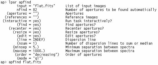
|
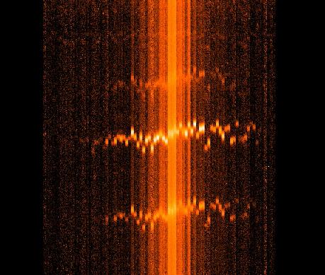
| ``Raw'' spectrum showing 82 spectra, left to right.
Shorter wavelengths are towards the top. Ha and [NII] emission are evident, as is a weak sky-line blue-wards of [NII] |
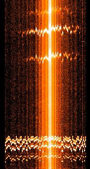
Radially ``re-Packed'' spectrum over the same wavelength range; the seven sky fibers are at the left edge. |
``Re-Packed'' spectrum showing strong sky lines |
 |
 |
 |
Repacking .ms files Because of both the of the complex nature of the mapping of the fibers from the telescope focal plane to the slit, it is difficult to interpret the extracted spectra, as output from, e.g., dohydra. This output is an "ms" file, i.e. an 82x2067 image, where each row is the extracted spectrum corresponding to fibers 1 to 82, respectively numbered according to the fiber position in the slit-block. One solution, suitable for a quick-look at the data, is to re-stack the spectra into meaningful orders. A simple iraf script and support files can be found here as part of an IRAF package named "ifupkg." Down-load this package and install it via an entry in your loginuser.cl. The script "repak.cl" allows you to take the output ms file from dohydra and repak the fibers so that they are ordered either radially (rad) outwards from the central fiber (#52), or stacked by rows oriented at a variety of position angles (pa[x]). The packing symmetry of the fibers allows for PAs of 0, 30, 60, 90, 120, and 150 degrees. The radial repacking is useful for inspection of S/N as a function of radius. The PA packing is useful for making a quick check on, e.g., whether the source has rotation, and a rough estimation of the position angle. Here's an example:
| raw ms |
rad | pa0 | pa30 | pa60 | pa90 | pa120 | pa150 | |
 |
NII Ha NII |
|||||||
For this source you can plainly see there is the least coherent spatial gradient is for PA near 90d (pa90), perhaps slightly offset towards PA of 120d. The kinematic major axis is there 90d offset from this PA, or roughly 10d. This agrees to within 10d of the value determined from a tilted-ring fit to the velocity field.
| |
|
|