| |
|
|
|
The scientific utility of a two-dimensional fiber array for the study of spatially resolved kinematics or line strengths and ratios is dramatic. Effectively, a fiber array allows one to 'image' the galaxy at high spectral resolution over a range in wavelength simultaneously. This is fabulously more efficient than Fabry-Perot imaging , and provides an easier and more reliable means of inspecting line-ratios since fluxes at all wavelengths are measured simultaneously. Fiber-fed echelle spectrographs with resolutions of 5000-20000 are straight-forward to build and maintain.
II. Project Description
We have successfully proposed to the NSF to build two fiber arrays
(IFUs) for the HET's MRS spectrograph for the study of spatially
resolved galaxy kinematics . Bershady (1997) briefly
outlines some of the key scientific issues to be addressed with these
instruments. Here we describe the base-line design. The final design
is likely to change, both in terms of fiber size, fiber lay-out, and
the total number of fibers. These changes will be documented here and
in the following section on program
progress.
Design: The fiber-coupled, bench-mounted design of the HET's Medium Resolution Spectrograph (MRS) is ideal for implementing a fiber array (Ramsey 1995). The spectrograph is designed to be highly stable, provide high red throughput (total system throughput of 10% at 0.9 microns), and resolutions of 10,900 for a 1 arcsec fiber. A 30mm spectrograph slit can accommodate up to roughly 270 0.5" fibers, or 135 1 arcsec fibers. While this is not enough to fully pave the 4 arcmin HET field-of-view, this is ample to design several fiber configurations that are particularly enticing for the measurement of galaxy kinematics over a wide range of redshift.
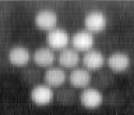
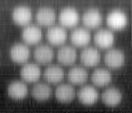
 The figures here illustrate designs for the two proposed fiber
arrays. The first array (left) uses 1 arcsec fibers (R=10,900) to
cover a 4.4 x 6.7 arcsec inner region with 'slits' extending to 31
arcsec (full length of major axis) at 4 position angles separated by
30 and 60 degrees. This is optimal sampling for an inclined disk to
discriminate between various components of the disk velocity
ellipsoid, while at the same time measuring rotation. With a packing
pattern where each row is shifted by half a fiber diameter, the inner
regions of the array will have a filling factor of 75%. This packing
pattern allows us to shift the diagonal slits to 30 and 60 degrees
from the major and minor axis and achieve the highest possible spatial
sampling. For typical, luminous spiral galaxies, spatial coverage
reaches radii of 18.4 kpc at redshifts as low as z=0.05, and
physical resolutions of ~4 kpc at z=0.3 (H0=75 km
s-1 Mpc-1). For comparison, typical luminous
spiral scale-lengths are roughly 5 kpc.
The figures here illustrate designs for the two proposed fiber
arrays. The first array (left) uses 1 arcsec fibers (R=10,900) to
cover a 4.4 x 6.7 arcsec inner region with 'slits' extending to 31
arcsec (full length of major axis) at 4 position angles separated by
30 and 60 degrees. This is optimal sampling for an inclined disk to
discriminate between various components of the disk velocity
ellipsoid, while at the same time measuring rotation. With a packing
pattern where each row is shifted by half a fiber diameter, the inner
regions of the array will have a filling factor of 75%. This packing
pattern allows us to shift the diagonal slits to 30 and 60 degrees
from the major and minor axis and achieve the highest possible spatial
sampling. For typical, luminous spiral galaxies, spatial coverage
reaches radii of 18.4 kpc at redshifts as low as z=0.05, and
physical resolutions of ~4 kpc at z=0.3 (H0=75 km
s-1 Mpc-1). For comparison, typical luminous
spiral scale-lengths are roughly 5 kpc.
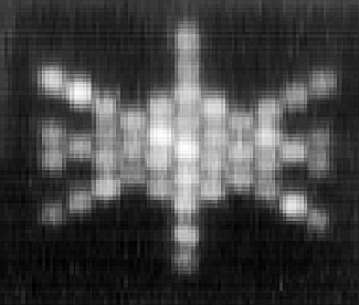
 The second array (left) is in the same spirit, but is designed for
higher spatial-resolution work. Using 0.5 arcsec fibers (R=21,800), a
6.5x9 arcsec inner region can be covered, with 'slits' extending to 15
arcsec at 4 position angles. Doubling spatial resolution provides a
physical resolution and coverage in the 0.15<z<0.3 regime comparable
to what can be achieved with the larger array between
0.05<z<0.15. Physical sampling on scales of 3-4 kpc to z=1 and beyond
is also acheived. While the median seeing at the HET site at
McDonald Observatory is 1 arcsec, the HET's queue scheduling will make
it possible to switch between arrays to take advantage of
sub-arcsecond seeing with the 0.5 arcsec fiber array.
The second array (left) is in the same spirit, but is designed for
higher spatial-resolution work. Using 0.5 arcsec fibers (R=21,800), a
6.5x9 arcsec inner region can be covered, with 'slits' extending to 15
arcsec at 4 position angles. Doubling spatial resolution provides a
physical resolution and coverage in the 0.15<z<0.3 regime comparable
to what can be achieved with the larger array between
0.05<z<0.15. Physical sampling on scales of 3-4 kpc to z=1 and beyond
is also acheived. While the median seeing at the HET site at
McDonald Observatory is 1 arcsec, the HET's queue scheduling will make
it possible to switch between arrays to take advantage of
sub-arcsecond seeing with the 0.5 arcsec fiber array.
Figure caption: Filled fibers go through to the spectrograph; remaining open fibers are for packing. The epoxy-bonded fiber layers are encased in a metal support structure. Ten sky fibers are attached to the support structure at telecentrically compensated angles (not shown). The filling factor is 75% in the coherent regions, assuming a 10:1 fiber core-to-clad ratio, and that the protective fiber buffers have been removed. (Lenslet-coupled arrays are currently under exploration; this would increase the filling factor to near unity.) Notice that the diagonal axes are at +/- 30 degrees from the major axis.
Performance: The MRS can spatially and spectrally sample both arrays with a minimum of 3 pixels in the direction of any one resolution element, assuming 0.15 micron CCD pixels. Given the HET's tracking instrument package at prime focus, typical integrations are 3000 seconds, and yield a 3:1 ratio of background shot-noise to detector read-noise at 0.55 microns (V band) using 1 arcsec fibers, assuming a CCD read-noise per un-binned pixel of 3e- (rms). Again taking the sky continuum to scale as lambda2.5 or lambda3, the product of background times total system throughput for the red beam of the MRS is constant or a rising function of lambda. Since background counts are proportional to this product, exposures will remain 3:1 background-limited or better to the 1 micron limit of the optical CCD. For 0.5 arcsec fibers, 1:1 background vs. read-noise limited performance can be achieved by binning the CCD in the spectral dimension, decreasing the resolution to around 8000. However, there are regions of the sky where the HET can expose for as long as 2-3 hours, thereby greatly improving the background-limited performance with the 0.5 arcsec array.
The HET's flat focal plane leads to a change in the telecentric angle over the 4 arcminute field-of-view. This in turn causes a change in the effective illumination across the field-of-view (technically, the focal-ratio degradation of the fibers is not constant). Over the inner 30 arcsec to 1 arcmin, this amounts to a 1-2% change in illumination, while at the edge of the field, the effect is as large as 10%. This implies that sky subtraction (and in fact all calibration) must be done with care. However, given the stability of both the fiber array and bench spectrograph, we will able to carefully calibrate this ``vignetting.'' In general, our ability to perform accurate sky subtraction will be greatly enhanced by working at high spectral resolution. At R=10,000, the atmospheric emission lines are well separated.
A near-infrared J and H band spectrograph will be contructed as a second beam of the MRS (thanks in part to some of the compelling argument made at several meetings -- see below.) The NIR beam will be fed with the direct light-path, while the red-optical ("yellow") beam will be split off via a dichroic after the fiber slit. The NIR beam will dramatically enhance our ability to track key red spectral at higher redshift, e.g. the CaII near-infrared triplet (~0.855 microns) to z=0.9, and H-alpha to z=1.5. These redshift limits are well beyond those imposed by surface-brightness dimming. The near-infrared beam of the MRS will improve upon the overall throughput at at lambda > 0.9 microns because of its higher detector efficiency. In this regime, even the 0.5 arcsec fiber array will be background-limited in 3,000 sec at full resolution of 21,800. The fibers for both arrays have uniform throughput all the way through the H band.
large postscript version
Constraints:
III. Deisgn YOUR IFU
Stay tuned -- this is under construction. 
| fiber size | Number of fibers | |||
| 20 mm slit | 25 mm slit | 30 mm slit | ||
| 1 arcsec | 200 microns | 83 | 104 | 125 |
| 1.5 arcsec | 300 microns | 55 | 69 | 83 |
| 2 arcsec | 400 microns | 41 | 52 | 62 |
The slit refers to the MRS slit length , where 20 mm is the base-line design; 25 mm may be possible with a collimator redesign and more money; 30 mm is asking a lot, but we have asked anyway because it really makes a difference! The total number of fibers assumes that they are packed "densely" together at the spectrograph slit with no separation, that the buffer is not stripped and that the clad and buffer are each 10% of the core.
Note that:
IV. Progress on NSF/AST-9618849
This section documents progress towards building two IFUs for the HETs
MRS under NSF/AST-9618849. Working on this project are: Matthew Bershady (PI), Larry Ramsey (co-I), and
Dave Andersen. As
usual, the person listed last is doing most of the work: Andersen, a
graduate student at Penn State supported under this grant, is the
person in the trenches building the IFUs, under Bershady's
supervision. He will be using them for his thesis research with the
HET. Ramsey is the HET project scientist and PI for the MRS. Other
players are Scott
Horner, and Leland Engel. Horner is the mover and shaker for the
Fiber Instrument Feed and will play a critical role in developing the
design constraints for the IFUs. Engel is the design engineer for all
of these subcomponents (HET, MRS, FIF, and IFUs). Sam Barden has
already played a critical role in advising us. The remainder of this
section is a rapidly evolving list documenting our tests and design
decisions.
Milestones: To be added.
Fiber Array Construction Jig: We borrowed the clever and elegant design used by Sam Barden for making Dense Pack and the new array on WIYN. Here are some sketches of the jig, by Dave Andersen (6/16/97): side, top, and bottom. Pictures, and notes on mechanical tolerance to be added.
Fiber Array Polishing Jig(s): Again, we borrowed the clever and simple design used by Sam Barden for making Dense Pack and the new array on WIYN. Sketches, pictures, and notes on polishing technique to be added.
Mounting hardware and FIF interface: TBD
Sky bundle and mount: TBD
Test Arrays: The goal here is a series of increasingly complicated and larger arrays culminating first in a 1 meter test bundle, and finally in the first of two full-length IFUs. The first several tests are designed to help us come up to speed on the glueing, packing, and polishing technique with different size fibers and fiber arrays.
Test Array #1
| ||||||||||||||||||||||||||||||||||||||||||||||
| Fiber type | Polymicro 400:440:480 micron core:clad:buffer | |||||||||||||||||||||||||||||||||||||||||||||
| Array size and configuration | 5 by 5 (O = long [6in]; x = short [3in]):
| |||||||||||||||||||||||||||||||||||||||||||||
| Glued length and glue type | 3 in., Epotek 354 | |||||||||||||||||||||||||||||||||||||||||||||
| Glue date(s) | July 15, 1997; July 17, 1997 acetone stripped and reglued. | |||||||||||||||||||||||||||||||||||||||||||||
| Polish date(s) | TBD | |||||||||||||||||||||||||||||||||||||||||||||
| Comments: First gluing - deposited glue while fibers were in the jig trench. Not sure edge fibers were well bonded, although good packing overall. End alignment could be improved, starting with pre-taped slits. Undid first glue after 24 hours of drying under 60 W lamp. Epoxy still fluid (5-day pot life). Cleaned well with acetone. Second gluing - deposited glue on fibers outside jig and then set in trench. Better end alignment becasue we paid attention to this. Had to play with jig width once glued fibers were stacked to get good packing. This forces glue out of the ends. More notes on gluing are here. Dry with UV lamp for heat. How long ? -- TBD. | ||||||||||||||||||||||||||||||||||||||||||||||
Test Array #2
| ||||||||||||||||||||||||||||||||||||||||||||||||||||||||||||||||||||||||||||||||||||||||||||||||||||||||||||||||||||||||||||||||||||||||||||||||||||||||||||||||||||||||||||||||||||||||||||||||||||||||||||||||||
| Fiber type | Polymicro 200:220:240 micron core:clad:buffer | |||||||||||||||||||||||||||||||||||||||||||||||||||||||||||||||||||||||||||||||||||||||||||||||||||||||||||||||||||||||||||||||||||||||||||||||||||||||||||||||||||||||||||||||||||||||||||||||||||||||||||||||||
| Array size and configuration | 10 by 11 (O = [6in]; x = short [3in]):
| |||||||||||||||||||||||||||||||||||||||||||||||||||||||||||||||||||||||||||||||||||||||||||||||||||||||||||||||||||||||||||||||||||||||||||||||||||||||||||||||||||||||||||||||||||||||||||||||||||||||||||||||||
| Glued length and glue type | TBD | |||||||||||||||||||||||||||||||||||||||||||||||||||||||||||||||||||||||||||||||||||||||||||||||||||||||||||||||||||||||||||||||||||||||||||||||||||||||||||||||||||||||||||||||||||||||||||||||||||||||||||||||||
| Glue date(s) | TBD | |||||||||||||||||||||||||||||||||||||||||||||||||||||||||||||||||||||||||||||||||||||||||||||||||||||||||||||||||||||||||||||||||||||||||||||||||||||||||||||||||||||||||||||||||||||||||||||||||||||||||||||||||
| Polish date(s) | TBD | |||||||||||||||||||||||||||||||||||||||||||||||||||||||||||||||||||||||||||||||||||||||||||||||||||||||||||||||||||||||||||||||||||||||||||||||||||||||||||||||||||||||||||||||||||||||||||||||||||||||||||||||||
| Comments: | ||||||||||||||||||||||||||||||||||||||||||||||||||||||||||||||||||||||||||||||||||||||||||||||||||||||||||||||||||||||||||||||||||||||||||||||||||||||||||||||||||||||||||||||||||||||||||||||||||||||||||||||||||
Test Array #3
| ||||||||||||||||||||||||||||||||||||||||||||||||||||||||||||||||||||||||||||||||||||||||||||||||||||||||||||||||||||||||||||||||||||||||||||||||||||||||||||||||||||||||||||||||||||||||||||||||||||||||||||||||||||||||||||||||||||||||||||||||||||||||||||||||||||||||||||||||||||||||||||||||||||||||||||||||||||||||||||||||||||||||||||||||||||||||||||||||||||||||||||||||||||||||||||||||||||||||||||||||||||||
| Fiber type | Polymicro 400:440:480 micron core:clad:buffer | |||||||||||||||||||||||||||||||||||||||||||||||||||||||||||||||||||||||||||||||||||||||||||||||||||||||||||||||||||||||||||||||||||||||||||||||||||||||||||||||||||||||||||||||||||||||||||||||||||||||||||||||||||||||||||||||||||||||||||||||||||||||||||||||||||||||||||||||||||||||||||||||||||||||||||||||||||||||||||||||||||||||||||||||||||||||||||||||||||||||||||||||||||||||||||||||||||||||||||||||||||||
| Array size and configuration | 14 by 15 (O = [6in]; x = short [3in]):
| |||||||||||||||||||||||||||||||||||||||||||||||||||||||||||||||||||||||||||||||||||||||||||||||||||||||||||||||||||||||||||||||||||||||||||||||||||||||||||||||||||||||||||||||||||||||||||||||||||||||||||||||||||||||||||||||||||||||||||||||||||||||||||||||||||||||||||||||||||||||||||||||||||||||||||||||||||||||||||||||||||||||||||||||||||||||||||||||||||||||||||||||||||||||||||||||||||||||||||||||||||||
| Glued length and glue type | TBD | |||||||||||||||||||||||||||||||||||||||||||||||||||||||||||||||||||||||||||||||||||||||||||||||||||||||||||||||||||||||||||||||||||||||||||||||||||||||||||||||||||||||||||||||||||||||||||||||||||||||||||||||||||||||||||||||||||||||||||||||||||||||||||||||||||||||||||||||||||||||||||||||||||||||||||||||||||||||||||||||||||||||||||||||||||||||||||||||||||||||||||||||||||||||||||||||||||||||||||||||||||||
| Glue date(s) | TBD | |||||||||||||||||||||||||||||||||||||||||||||||||||||||||||||||||||||||||||||||||||||||||||||||||||||||||||||||||||||||||||||||||||||||||||||||||||||||||||||||||||||||||||||||||||||||||||||||||||||||||||||||||||||||||||||||||||||||||||||||||||||||||||||||||||||||||||||||||||||||||||||||||||||||||||||||||||||||||||||||||||||||||||||||||||||||||||||||||||||||||||||||||||||||||||||||||||||||||||||||||||||
| Polish date(s) | TBD | |||||||||||||||||||||||||||||||||||||||||||||||||||||||||||||||||||||||||||||||||||||||||||||||||||||||||||||||||||||||||||||||||||||||||||||||||||||||||||||||||||||||||||||||||||||||||||||||||||||||||||||||||||||||||||||||||||||||||||||||||||||||||||||||||||||||||||||||||||||||||||||||||||||||||||||||||||||||||||||||||||||||||||||||||||||||||||||||||||||||||||||||||||||||||||||||||||||||||||||||||||||
| Comments: Note buffer fibers in this design. | ||||||||||||||||||||||||||||||||||||||||||||||||||||||||||||||||||||||||||||||||||||||||||||||||||||||||||||||||||||||||||||||||||||||||||||||||||||||||||||||||||||||||||||||||||||||||||||||||||||||||||||||||||||||||||||||||||||||||||||||||||||||||||||||||||||||||||||||||||||||||||||||||||||||||||||||||||||||||||||||||||||||||||||||||||||||||||||||||||||||||||||||||||||||||||||||||||||||||||||||||||||||
Test Array #4 | |
| Fiber type | Polymicro 400:440:480 micron core:clad:buffer |
| Array size and configuration | 14 by 15 (O = [1m]; x = short [3in]):
|
| Glued length and glue type | TBD |
| Glue date(s) | TBD |
| Polish date(s) | TBD |
| Comments: full test version. | |
Test Array #5 | |
| Fiber type | Polymicro 400:440:480 micron core:clad:buffer |
| Array size and configuration | 5 by 5 (O = [6in]; x = short [1in]):
|
| Glued length and glue type | TBD |
| Glue date(s) | TBD |
| Polish date(s) | TBD |
| Comments: Note short packing fibers in this design. | |
| |
|
|
|