Rigorous Coupled-Wave Analysis (RCWA):
We calculate the efficiency within a bandpass between 380-680 nm at 1 nm resolution for a 3550 l/mm grating at an incidence angle of 65 deg in first order. The calculation is repeated over a grid in mean index (5 values of n2 = 1.37, 1.40, 1.43, 1.46, 1.50), DCG index modulation (64 values dlogn from 0.005 to 0.1), and DCG thickness (70 values of D from 0.5 to 35 microns). The last n2 value (1.50) was done later, and is the adopted CSL target value. At each grid point we have evaluated the the bandpass in terms of:
- peak diffraction efficiency
- wavelength at peak diffraction efficiency
- W50: the full width at half-maximum diffraction efficiency
- S50: the equivalent width within W50
General conclusions:
- Larger mean DCG index (n2) yields better performance.
- For a given width or peak efficiency, there is a covariance of between DCG thickness and index modulation.
- The best-performance gratings (high efficiency and large bandpass) have thin DCG with large index modulation. This means making good gratings is challenging.
- There is a high-frequency periodicity to peak efficiency and
width in either DCG thickness or modulation. This makes tuning the
grating in the manufacturing process is tricky.
Satisfying Performance Requirements:
Specific Findings and Conclusions
2. Efficiency and Bandwidth: For four different mean DCG refractive indices (n2 = 1.37, 1.40, 1.43, 1.46) we have identified the minimum DCG index modulations and the matching thickness satisfying various peak efficiency and W50 performance criteria. These are tabulated and plotted below. Note WP3200 grating has mean DCG index of 1.4 and a maximum dn of 0.048, or dlogn = 0.034. CSL has indicated it may be able to achieve dn values of 0.076. This translates into dlogn = 0.55 - 0.52 for n2 = 1.37-1.4, respectively, assuming that dn = 0.076 is achievable for this range of n2.
- We conclude that our initial design
requirements are somewhat optimistic, but that the mean refractive
index, n2, of the DCG must be > 1.40 in order to approach the design
requirements.
- If n2 = 1.40, the bandwidth will be roughly half of our specification at 80% peak effciency.
- If n2 = 1.43-1.46, most of the specified bandwidth can be achieved at 80% peak effciency.
-
Table 1. Minimum dlogn to Achieve Efficiency and Bandwidth Criteria Peak
Diffraction
EfficiencyW50/lmax
(dl/l)n2
dlogn
D
(microns)Peak
Diffraction
EfficiencyW50/lmax
(dl/l)n2
dlogn
D
(microns)0.8 0.04 1.37 NA NA 0.9 0.04 1.37 NA NA 0.8 0.04 1.40 0.056 17.0 0.9 0.04 1.40 0.067 22.5 0.8 0.04 1.43 0.043 21.5 0.9 0.04 1.43 0.046 20.5 0.8 0.04 1.46 0.031 20.5 0.9 0.04 1.46 0.055 12.0 0.8 0.05 1.37 NA NA 0.9 0.05 1.37 NA NA 0.8 0.05 1.40 0.071 17.0 0.9 0.05 1.40 0.082 15.0 0.8 0.05 1.43 0.052 12.5 0.9 0.05 1.43 0.067 10.0 0.8 0.05 1.46 0.038 16.5 0.9 0.05 1.46 0.056 7.5 0.8 0.06 1.37 NA NA 0.9 0.06 1.37 NA NA 0.8 0.06 1.40 0.083 14.5 0.9 0.06 1.40 0.091 13.5 0.8 0.06 1.43 0.056 11.5 0.9 0.06 1.43 0.082 11.5 0.8 0.06 1.46 0.049 13.0 0.9 0.06 1.46 0.064 6.5 0.8 0.07 1.37 NA NA 0.9 0.07 1.37 NA NA 0.8 0.07 1.40 0.089 13.5 0.9 0.07 1.40 NA NA 0.8 0.07 1.43 0.068 9.5 0.9 0.07 1.43 0.089 10.5 0.8 0.07 1.46 0.055 11.5 0.9 0.07 1.46 0.076 5.5
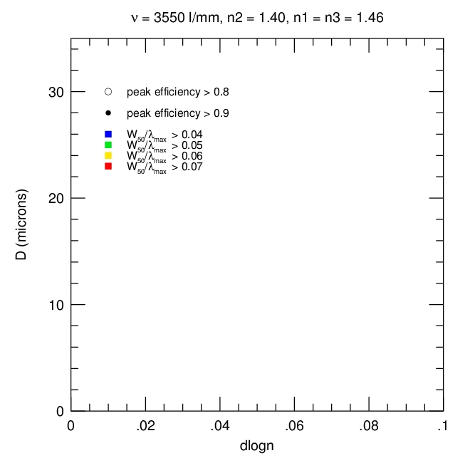
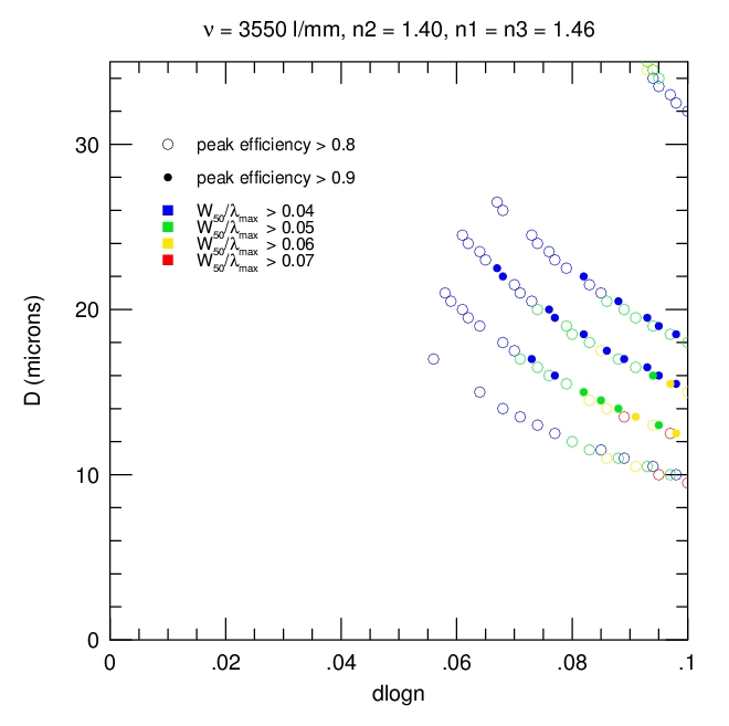
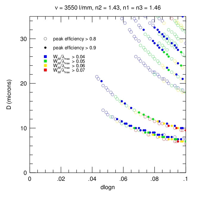
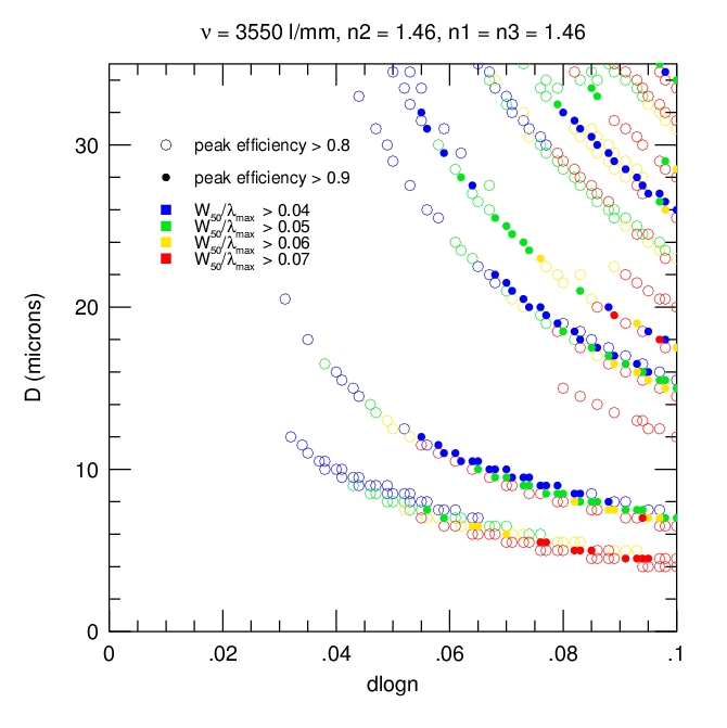
| Optimized D-DLOGN for different thresholds in peak diffraction efficiency and bandwidth (W50) and four DCG refractive indices, n2. (All cases: incidence angle of 65o, m = 1.) | |||
| n2=1.37 n1=n3=1.46, n1/n2 = 1.066 |
n2=1.40 n1=n3=1.46, n1/n2 = 1.043 |
n2=1.43 n1=n3=1.46, n1/n2 = 1.021 |
n2=1.46 n1=n3=1.46, n1/n2 = 1.000 |
 |
 |
 |
 |
RCWA D-DLOGN Maps: Peak Diffraction Efficiency, Width and Equivalent-Width
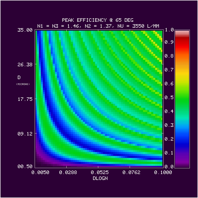
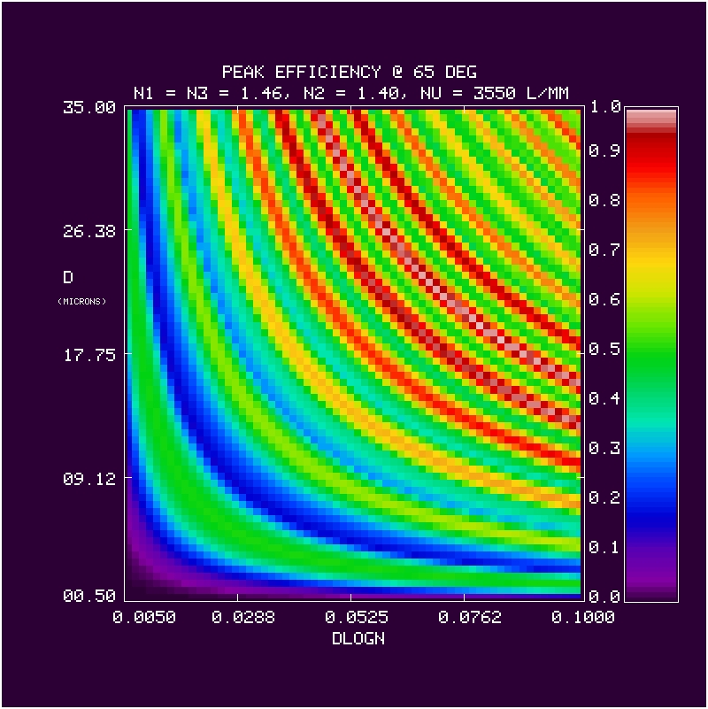
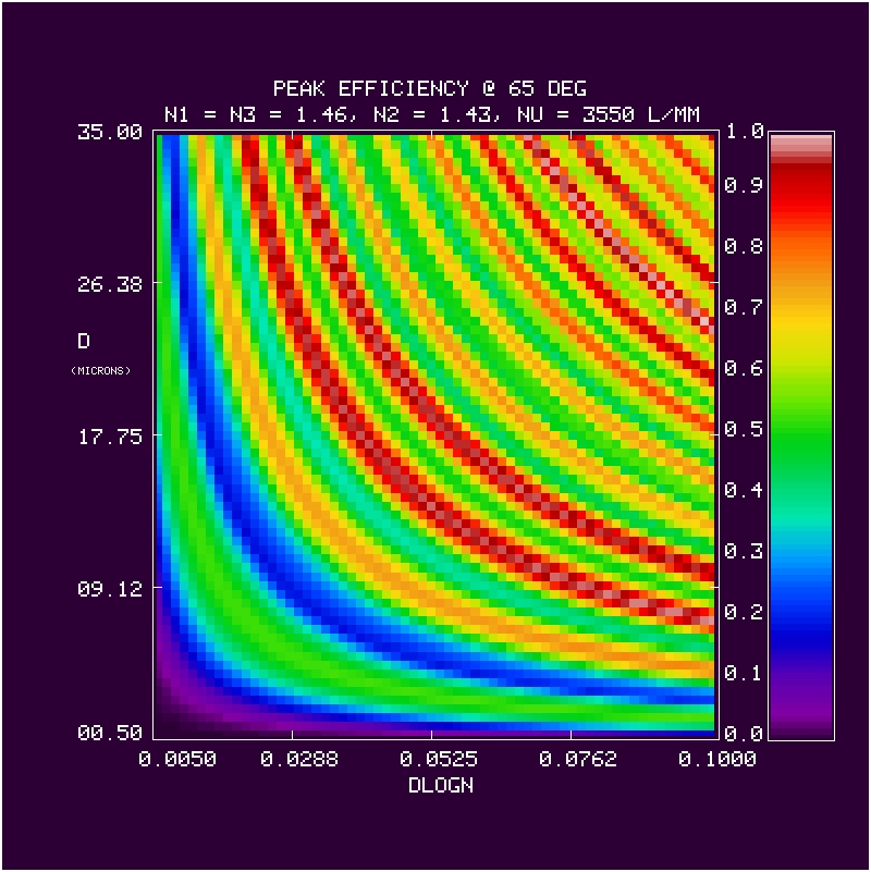
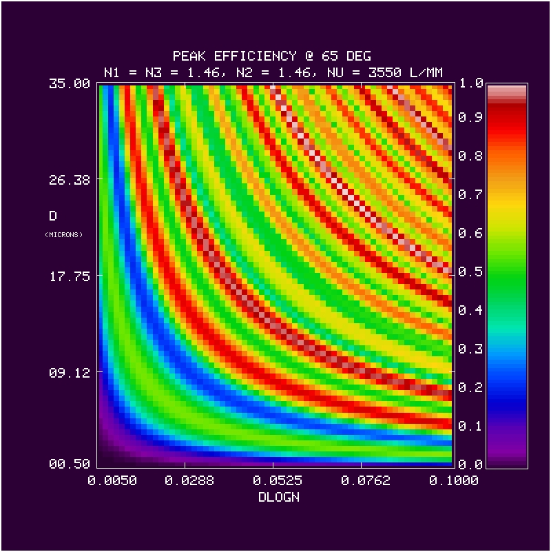
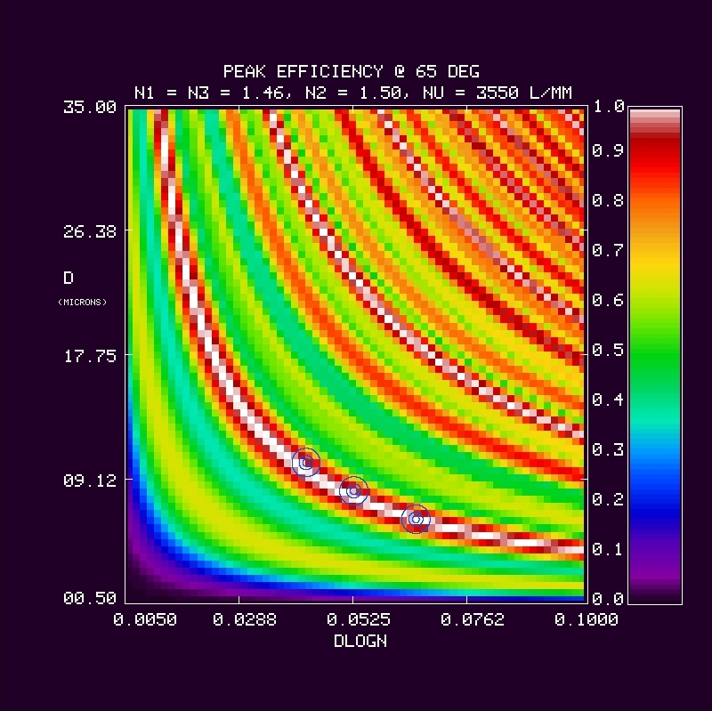
| Peak Diffraction Efficiency at 65o, m = 1, as a function of grating DCG thickness (D, in microns) and DCG index modulation (DLOGN = dn/n). Note circles in last panel for n2=1.50, which are 3 possible target values adopted by CSL, and are very close to the 2nd peak ridge-line (1st above 70%) at low d: d = (10,8,6) microns, dn = (0.063,0.078,0.010), and dlogn = (0.0420,0.0520,0.0667). | ||||
| n2=1.37 n1=n3=1.46, n1/n2 = 1.066 |
n2=1.40 n1=n3=1.46, n1/n2 = 1.043 |
n2=1.43 n1=n3=1.46, n1/n2 = 1.021 |
n2=1.46 n1=n3=1.46, n1/n2 = 1.000 |
n2=1.50 n1=n3=1.46, n1/n2 = 1.000 |
 |
 |
 |
 |
 |
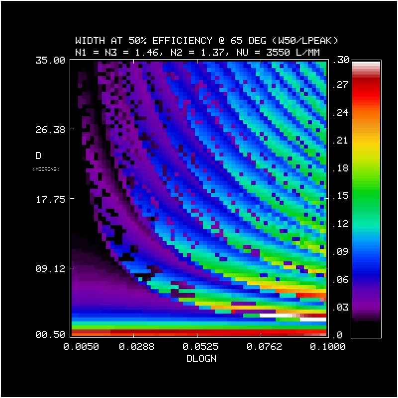
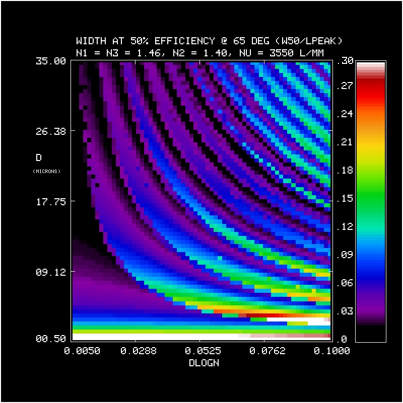
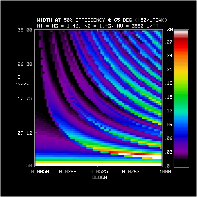
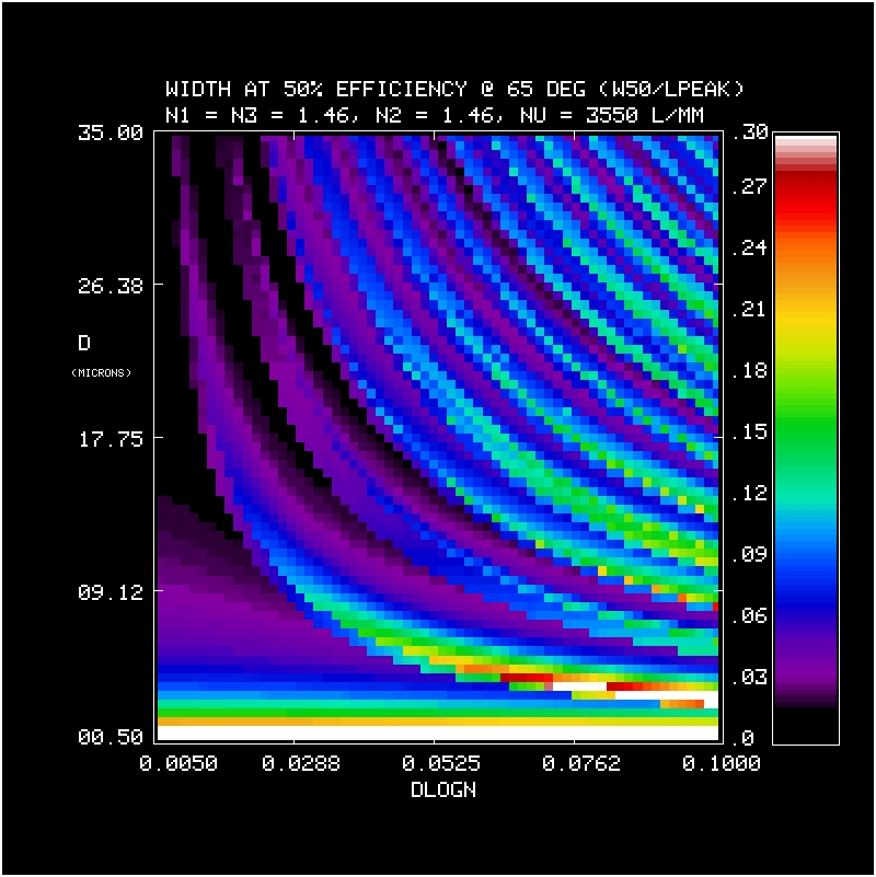
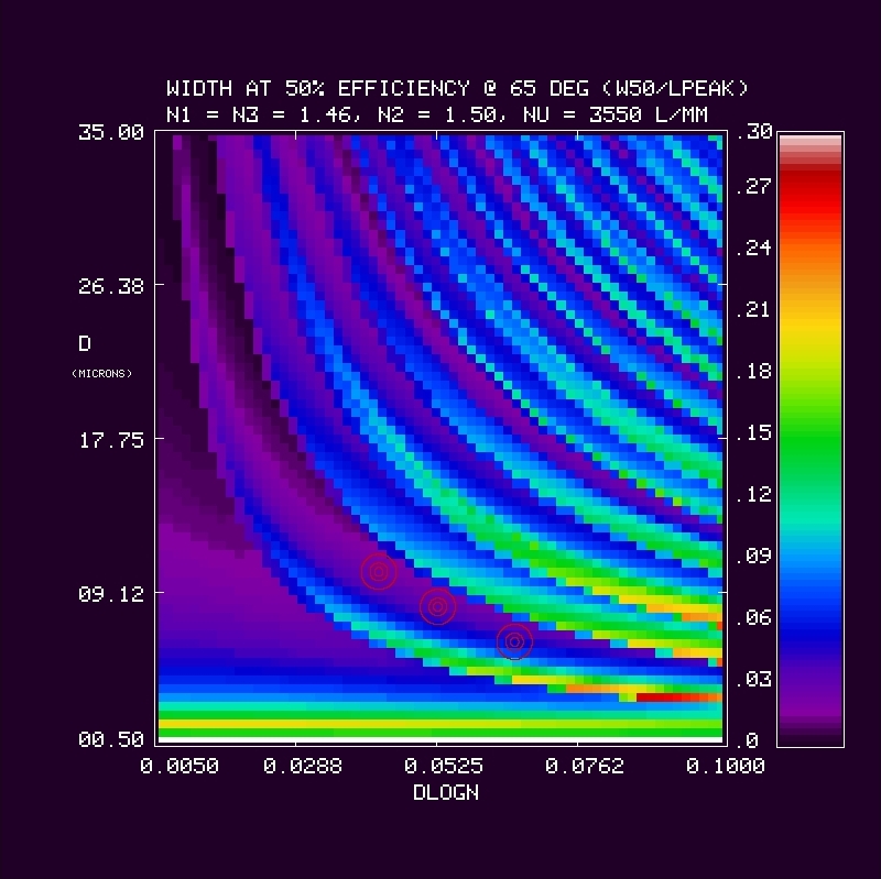
| Bandwidth at 50% Peak Diffraction Efficiency (W50) at 65o, m = 1, as a function of grating DCG thickness (D, in microns) and DCG index modulation (DLOGN = dn/n). Bandwidth is normalized by peak wavelength (lmax), i.e., W50 hasdimensionless units of dlambda/lambda. Note circles in last panel for n2=1.50, which are 3 possible target values adopted by CSL, and lie in a trough in width. The loweest d, highest dlogn has the best value. | ||||
| n2=1.37 n1=n3=1.46, n1/n2 = 1.066 |
n2=1.40 n1=n3=1.46, n1/n2 = 1.043 |
n2=1.43 n1=n3=1.46, n1/n2 = 1.021 |
n2=1.46 n1=n3=1.46, n1/n2 = 1.000 |
n2=1.50 n1=n3=1.46, n1/n2 = 1.000 |
 |
 |
 |
 |
 |
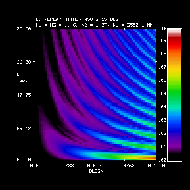
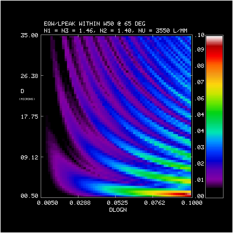
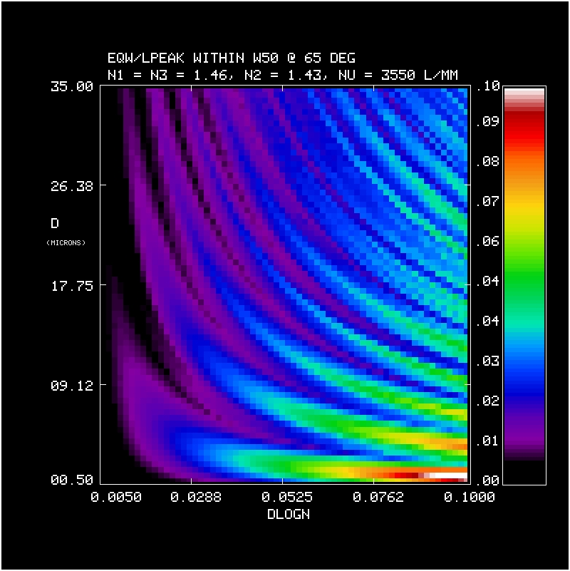
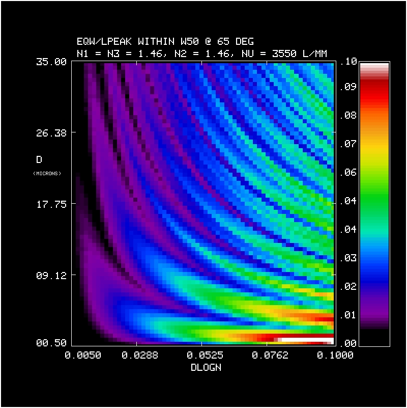
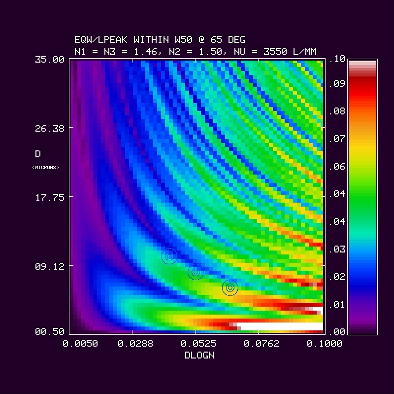
| Equivalent Width of Bandpass within 50% Peak Diffraction Efficiency at 65o, m = 1, as a function of grating DCG thickness (D, in microns) and DCG index modulation (DLOGN = db/n). This is the effective bandwidth at 100% efficiency within the FWHM of the true bandpass. For a given FWHM bandwidth, larger effective band-widths indicate higher efficiency; for a given FWHM and peak efficiency, larger effective bandwidths indicate a more square-shaped (platykurtic) bandpass. Again, this effective bandwidth is normalized by peak wavelength, i.e., dimensionless units of dlambda/lambda. Note circles in last panel for n2=1.50, which are 3 possible target values adopted by CSL, and lie on the edge of the 2nd ridge. The lowest D, highest dlogn has the best value. | ||||
| n2=1.37 n1=n3=1.46, n1/n2 = 1.066 |
n2=1.40 n1=n3=1.46, n1/n2 = 1.043 |
n2=1.43 n1=n3=1.46, n1/n2 = 1.021 |
n2=1.46 n1=n3=1.46, n1/n2 = 1.000 |
n2=1.50 n1=n3=1.50, n1/n2 = 1.000 |
 |
 |
 |
 |
 |
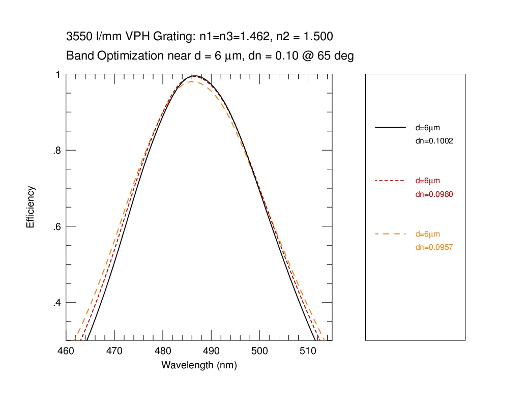
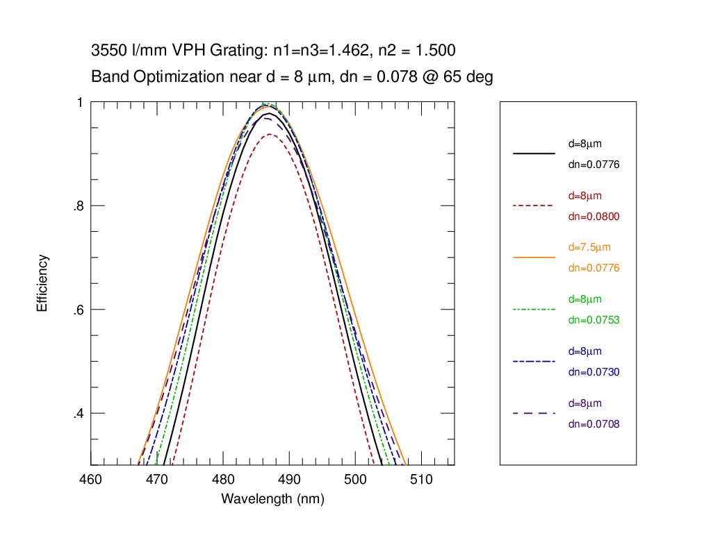
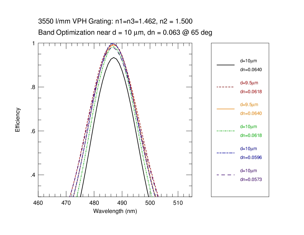
Optimization at 65 degrees
| Nominal Values: |
d = 6 microns | d = 8 microns | d = 10 microns |
| dn = 0.1 | dn = 0.078 | dn = 0.063 | |
 |
 |
 |
CONCLUSIONS: