WIYN / Bench Rebuild: |
| Grating Basics | Maximum Size | Maximum Angle | Science Optimization | Proposed Parameters | Grating Optimization | Expected Performance | Delivered Product | Testing |
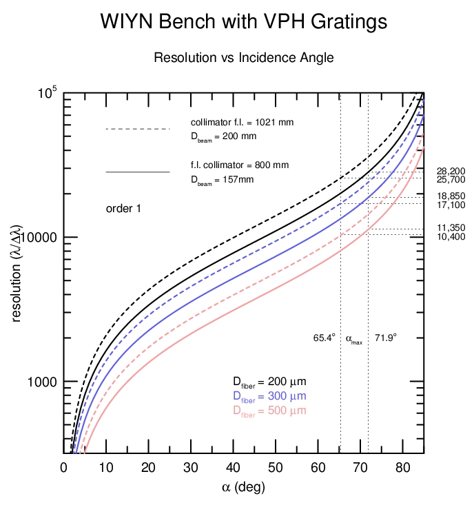
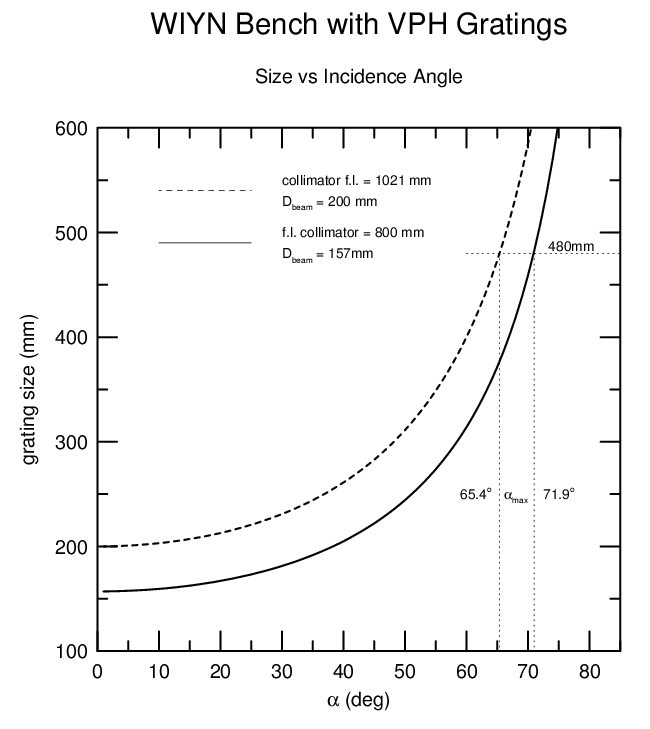
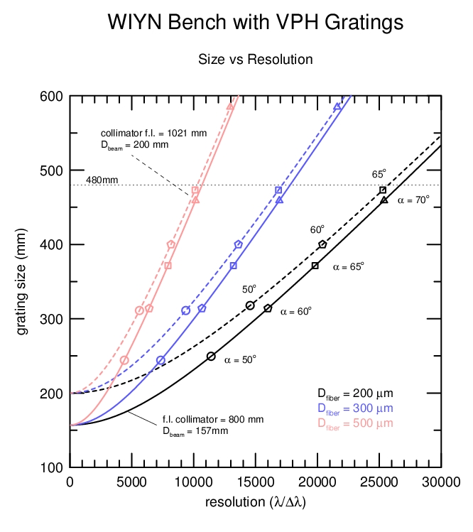 These three plots show the following coupled relations for
first-order VPH gratings used on the bench:
These three plots show the following coupled relations for
first-order VPH gratings used on the bench:1. Resolution (R = lambda/dlambda) vs incidence angle (alpha): R = 2 * (fl/w)) * tan(alpha), where fl is the collimator focal length and w is the effective slit width.
2. Grating size (Dgrating) vs incidence angle (alpha): Dgrating = Dbeam/cos(alpha), where Dbeam is the effective collimated beam diameter.
3. Grating size (Dgrating) vs resolution (R), with quantities defined as above.
In all cases we have considered the two relevant collimator focal lengths: 1021mm (current) and 800mm (adopted upgrade); and 3 effective slit-widths for 200, 300, and 500 micron diameter fibers. The effective slit width is the FWHM, which for a circular fiber is cos(30) = 0.866 of the diameter. This table summarizes the effective slit widths for WIYN Bench fiber cables, and gives the reimaged effective slit widths (at the CCD) for de-magnifications of 3.58 and 2.81 corresponding to a camera effective focal length of 285mm and collimator focal lengths of 1021mm and 800mm, respectively:
| fiber diameter (microns) | 200 | 300 | 500 |
| effective slit-width (microns) | 173 | 260 | 433 |
| image size with collimator fl=1021mm (microns) | 48 | 73 | 121 |
| image size with collimator fl=800mm (microns) | 62 | 92 | 154 |
1. Higher resolutions are possible for the same size grating with the shorter focal length collimator because the smaller effective collimated beam allows for larger unvignetted angles and higher dispersion that more than compensates for the increased magnification. At a given resolution, the wavelength coverage will be greater with the longer focal-length collimator (smaller angular dispersions yield equivalent spectral resolution with smaller magnificaion). However, this comes at the monetary cost of a larger grating and at lower throughput because of vignetting in the camera.
2. Resolutions of 28,000 are possible with a 480 mm clear aperture VPH grating and the smallest existing (200 micron) fibers.
Notes: (i) To realize the gains from the faster collimator
requires good grating coatings with high efficiency at large
angles. (ii) Larger dispersions may be obtained at smaller angles
and gratings with 2nd order gratings or two gratings used in
series. Both of these options are possible, and will be considered
later, elsewhere.
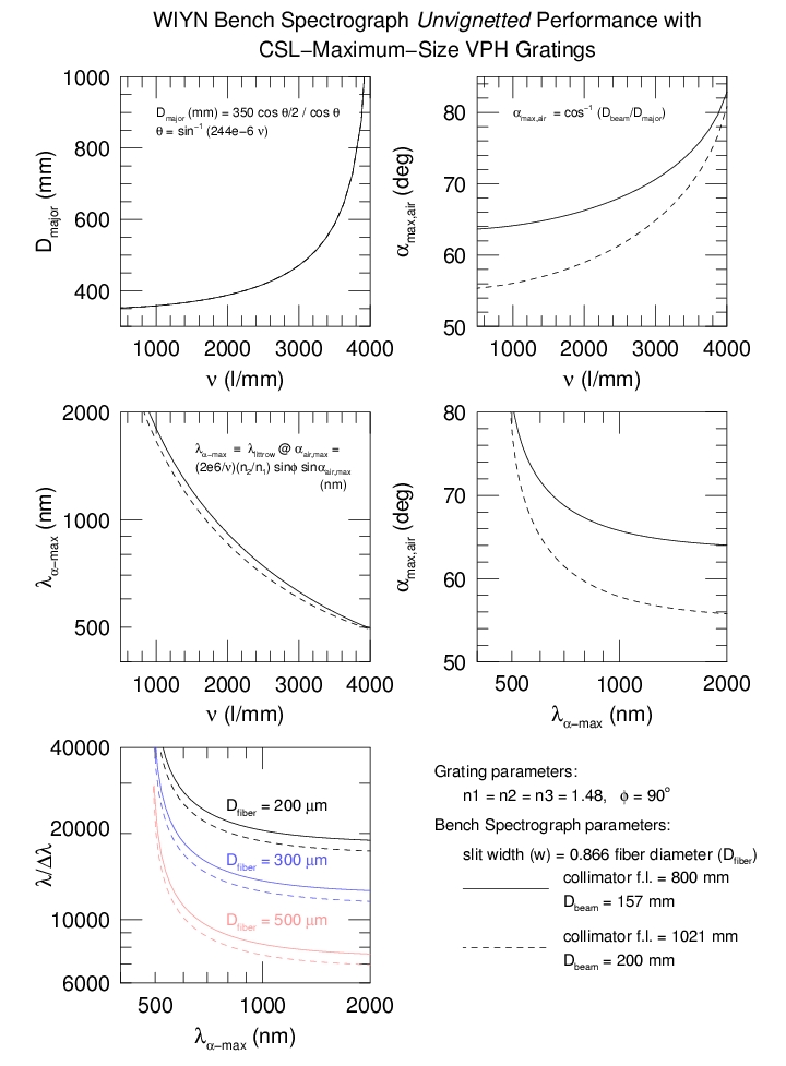 This set of plots shows the relationship between nu and the grating
major axis size (Dmajor), and the resulting relationships
between nu, the maximum grating angle (alphamax,air),
wavelength, and maximum spectral resolution. The wavelength
lambdaalpha-max is the central wavelength at the maximum
incidence angle (alphamax,air) for a Littrow configuration
(incidence and diffracted angles relative to groove plane are equal)
where the grating is unvignetted.
This set of plots shows the relationship between nu and the grating
major axis size (Dmajor), and the resulting relationships
between nu, the maximum grating angle (alphamax,air),
wavelength, and maximum spectral resolution. The wavelength
lambdaalpha-max is the central wavelength at the maximum
incidence angle (alphamax,air) for a Littrow configuration
(incidence and diffracted angles relative to groove plane are equal)
where the grating is unvignetted.
These relationships are for Littrow gratings choosing maxima to be the largest unvignetted configuration for a given line frequency (hence, these are a function of beam size). Spectral resolution also depends on the ratio of collimator focal length to slit width f1/w. The two examples shown are for the existing Bench collimator and the planned, shorter off-axis collimator.
CONCLUSIONS:
1. The highest spectral resolutions with VPH gratings are obtainable at blue/visible wavelengths for unvignetted systems. A confluence of three (3) facts lead to this: The highest dispersions are achievad at the largest grating angles; grating size increases with line density (l/mm); and wavelength decreases with increasing line density for a given incidence angle. For the Bench, resolutions above 10,000 are achievable below 650nm for 500 micron diameter fibers; resolutions above 20,000 are achievable below 550nm for 300 micron diameter fibers; resolutions above 30,000 are achievable below 550nm for 200 micron diameter fibers.
2. Note again that higher spectral resolutions are achievable in unvignetted (i.e., high throughput) configurations with a shorter focal-length collimator: smaller beam size allows for larger incidence angles which trumps increased magnification.
Example: A 500mm x 230mm CSL grating would have a maximum unvignetted incidence angles (alpha) of 72.5 deg for a 150mm collimated beam, or 66.4 deg for a 200mm collimated beam. For typical gelatin indices (1.43) these angles correspond to grating incidence angles in the gelatin of 41.8 and 39.8 degrees. On the Bench Spectrograph with a 800mm effective focal-length collimator the 150mm and 200mm beams enclose 87% and 97% of the total light emergent from the fibers.
Reality: The cost of substrates is a strong function of size. Substrates over 400mm are very expensive, with few companies willing to bid. Nonetheless we have settled on a final high-density grating size of 480 x 210 mm clear aperture (500 x 230 x 30 mm substrate), and contracted with Zygo for delivery in July 2004. The maximum unvignetted angle with 480mm clear aperture is 71.8 deg.
The above excerise shows that higher resolutions are achievable if the higher cost is acceptable. Note reflection loss and coating issues below.
| Air-Glass % Reflection Losses Per Surface | Uncoated | Newport Thin Film | Spectrum Thin Film | |
| Angle | 400-500nm | 500-550nm | 450-550nm | |
| 55o | 6 | 2.5 | 2 | < 1 |
| 60o | 3.5 | 2.5 | ||
| 65o | 11 | 5.5 | 4.5 | < 2 |
| 70o | 9.5 | 7.5 | ||
| 75o | 24 | 17 | 15.5 | < 7 |
CONCLUSION: Losses above 70o are prohibitive with current coating technology. Optimize grating design up to 70o, with acceptable performance up to 75o.
Optimum wavelength range. There are two guiding principles on where to center the band-pass of the super-blaze: (1) Coverage of desired spectral features; (2) optimization of spectral resolution for particular spectral features.
One constraint is that for roughly 3300 l/mm gratings we will get the following range of incidence angles where the blaze peak (at a given angle) is above the listed thresholds.
| blaze peak | delta-alpha | delta-lambda | > 80% | 15 | 100 |
| > 70% | 20 | 115 |
| > 60% | 23 | 140 |
The next consideration are the following spectral features of interest, or of interest to avoid:
| Hdelta | 410.1 nm | Hbeta | 486.1 nm | SKY | 557.7 nm |
| CaI | 422.6 | [OIII] | 495.9 | HeI | 587.5 |
| G | 430.4 | [OIII] | 500.7 | Na | 589.2 |
| Hgamma | 434.0 | MgI | 513.0 | ||
| Fe | 438.4 | Ca+Fe | 526.9 |
The last consideration is redshift. For DensePak and SparsePak work, galaxies out to recession velocities of 10,000-12,000 km/s are common targets. Hence factors of 1.04 should be applied to the above spectral table to spread the desired range to the red.
We conclude a range of 445-545 nm for the superblaze W80 is a near-optimal trade between coverage of features at high throughput, optimization for resolution near the MgI feature at rest and redshifted, and staying blueward of the 557.7 nm sky line. W80 is the width of the superblaze (in wavelength) where the blaze peak at any given angle is > 80% of the superblaze peak.
The usable wavelength range of the graing is considerably larger.
| PROPOSED WP4200 DESIGN PAREMETERS | ||
| ``Requirement" | Best Effort | |
| line-frequency: | 3550 l/mm | |
| superblaze peak wavelength: | 510.6 nm @ 65o | |
| superblaze peak efficiency: | > 90% | |
| range of incidence angles with blaze peak at > 80% superblaze peak (> 70% absolute*): |
55-70o | up to 72 o |
| wavelength range of blaze peak at > 80% superblaze peak (> 70% absolute*): |
461-530 nm | up to 535 nm |
| wavelength range @ 55o at > 80% blaze peak (> 60% absolute*): |
> 28nm | |
| wavelength range @ 65o at > 80% blaze peak (> 70% absolute*): |
> 21nm | |
| wavelength range @ 70o at > 80% blaze peak (> 60% absolute*): |
> 17nm | |
*Grating efficiencies do not include air-glass reflection losses.
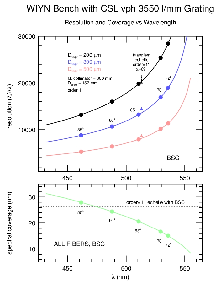 This plot shows the spectral resolution and coverage
as a function of central wavelength for the proposed 3550 l/mm VPH
grating to be manufactured by CSL. Indicated on the plot are the 5
incidence angles (alpha) between 55 and 72 degrees between which the
grating efficiency will be optimized. The performance is calculated
for the three fiber feed diameters. The spectral coverage is the same
for all fibers. The following is a table of values for labeled
angles:
This plot shows the spectral resolution and coverage
as a function of central wavelength for the proposed 3550 l/mm VPH
grating to be manufactured by CSL. Indicated on the plot are the 5
incidence angles (alpha) between 55 and 72 degrees between which the
grating efficiency will be optimized. The performance is calculated
for the three fiber feed diameters. The spectral coverage is the same
for all fibers. The following is a table of values for labeled
angles:
| Spectral Resolution and Coverage vs Angle for 3550 l/mm VPH Grating1 | |||||||
| alpha (deg) |
Central Wavelength (nm) |
Blue Wavelength (nm) |
Red Wavelength (nm) |
Wavelength Coverage (nm) |
Spectral Resolution (Dfiber = 200 mu) |
Spectral Resolution (Dfiber = 300 mu) |
Spectral Resolution (Dfiber = 500 mu) |
| 55 | 461.5 | 446.7 | 474.6 | 27.9 | 13190 | 8795 | 5277 |
| 60 | 487.9 | 474.8 | 499.2 | 24.4 | 16000 | 10670 | 6400 |
| 65 | 510.6 | 499.3 | 519.9 | 20.6 | 19810 | 13210 | 7924 |
| 70 | 529.4 | 520.1 | 536.7 | 16.7 | 25380 | 16920 | 10150 |
| 72 | 535.8 | 527.3 | 542.3 | 15.1 | 28430 | 18950 | 11370 |
| Spectral Resolution and Coverage vs Angle for 316@63.4 Echelle (order 11) | |||||||
| 69 | 513.1 | 500.0 | 526.2 | 26.2 | 200502,3 200501,4 |
197002 144401 |
117472 86651 |
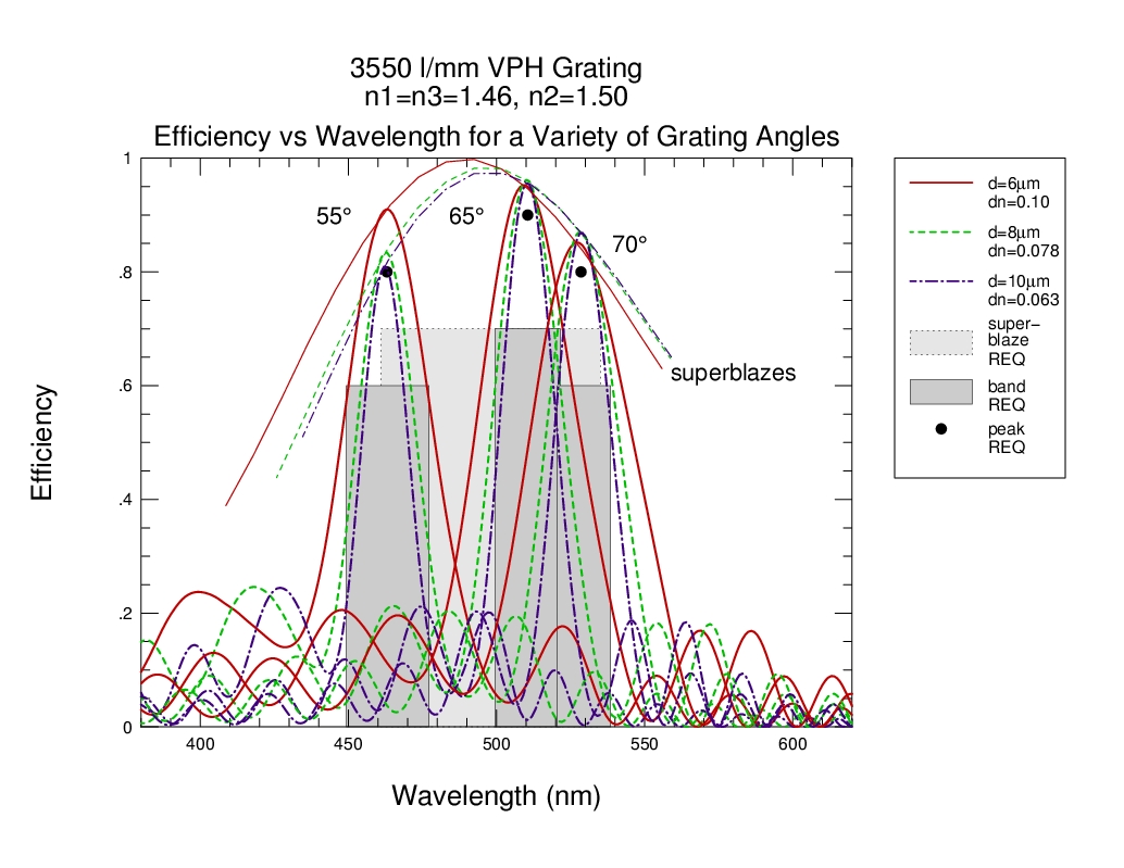 Overview Figure. These are the RCWA predicted grating
diffraction efficiencies in first order for the 3550 l/mm grating for
the set of three gelatin-thickness and index-modulation parameters
proposed by CSL. All three meet or exceed peak and super-blaze
efficiency requirements; only the case for the highest
index-modulation and thinnest gelatin meets the band-width
requirements. THESE CURVES DO NOT INCLUDE REFLECTION LOSSES (see this table).
Overview Figure. These are the RCWA predicted grating
diffraction efficiencies in first order for the 3550 l/mm grating for
the set of three gelatin-thickness and index-modulation parameters
proposed by CSL. All three meet or exceed peak and super-blaze
efficiency requirements; only the case for the highest
index-modulation and thinnest gelatin meets the band-width
requirements. THESE CURVES DO NOT INCLUDE REFLECTION LOSSES (see this table).Assuming the highest index-modulation is achieved, compared to the current echelle:
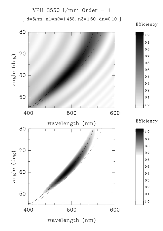
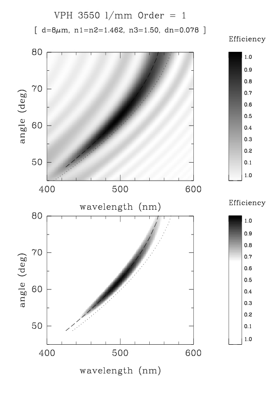
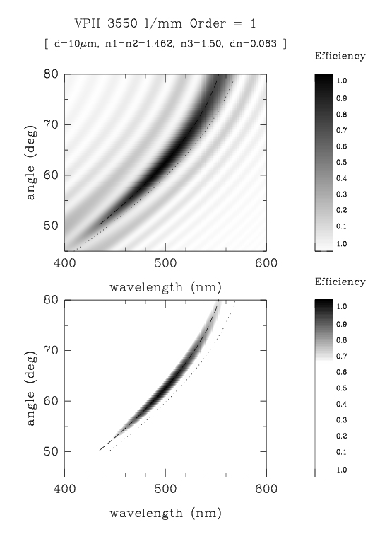
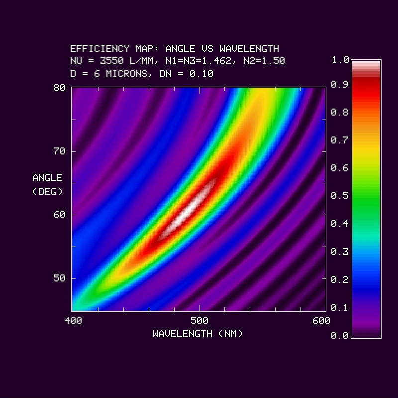
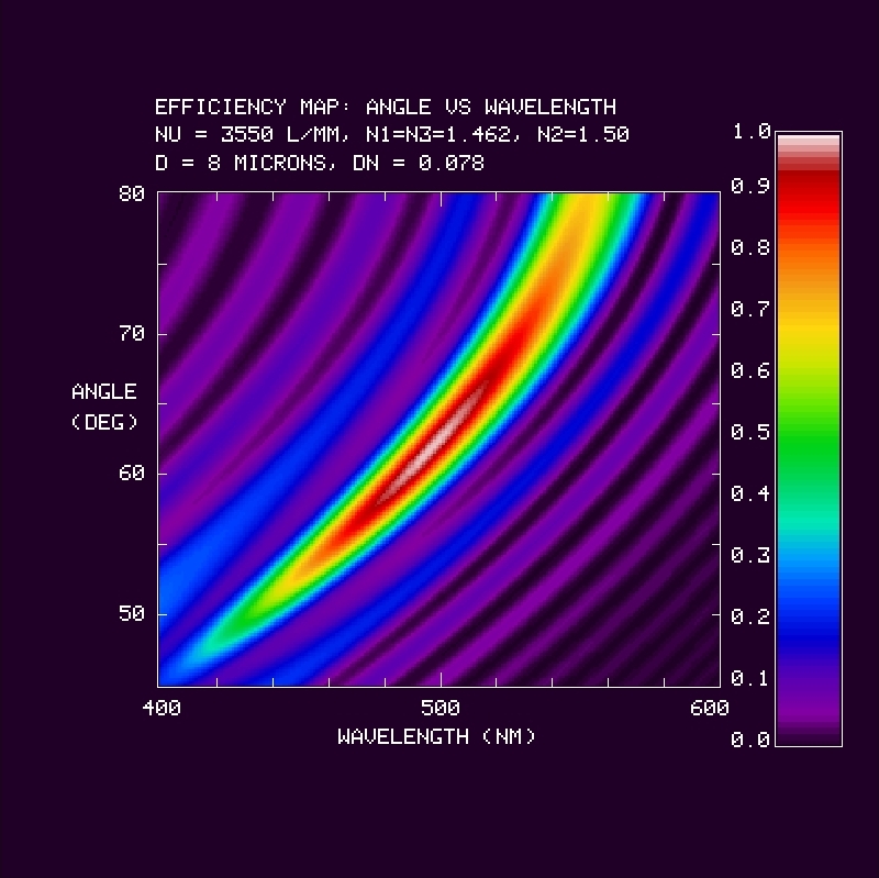
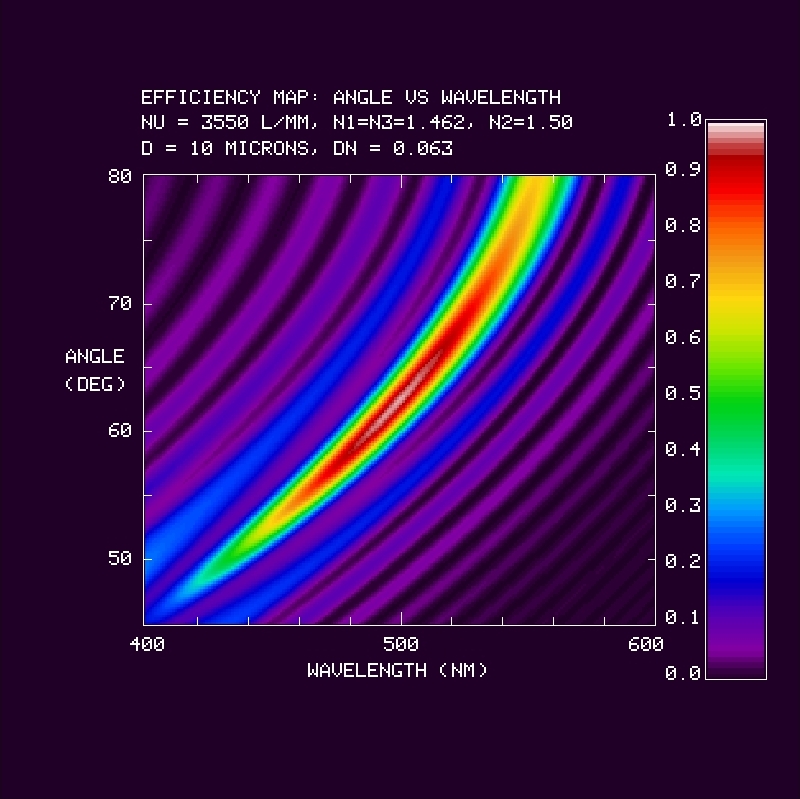
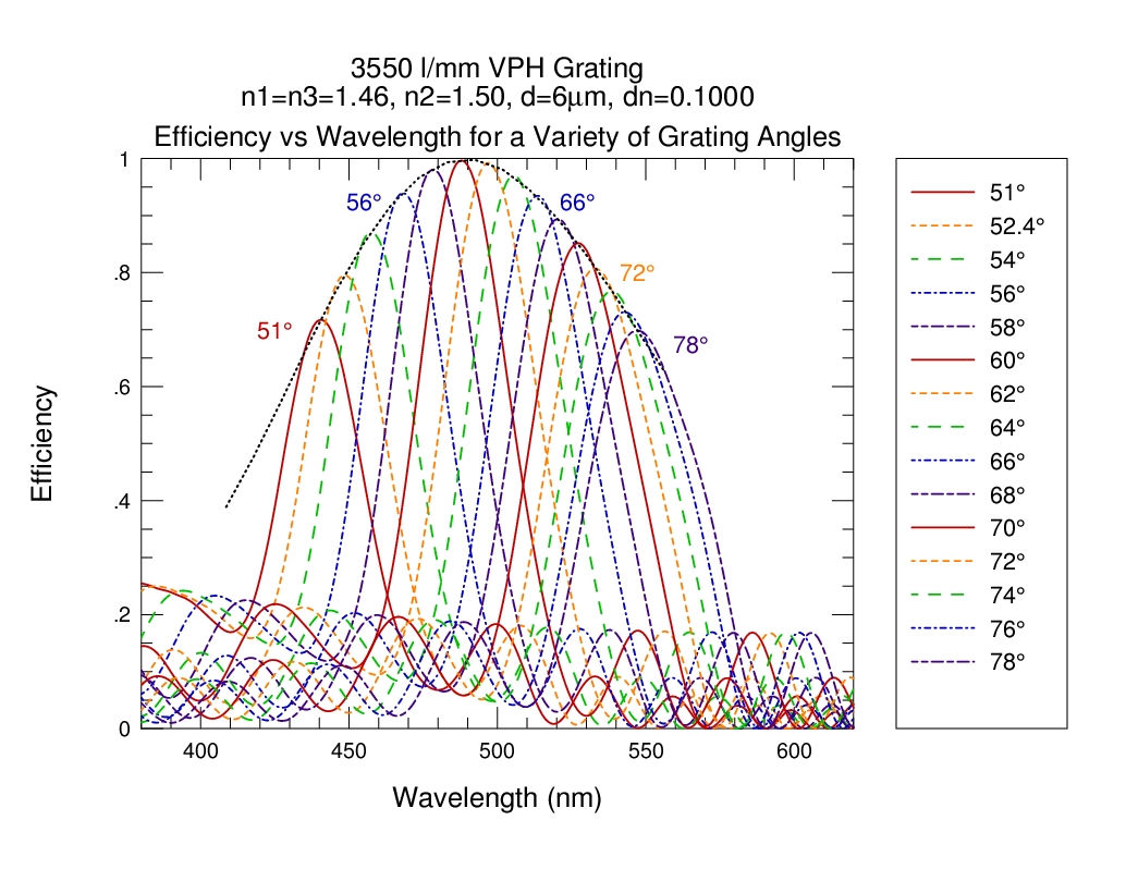
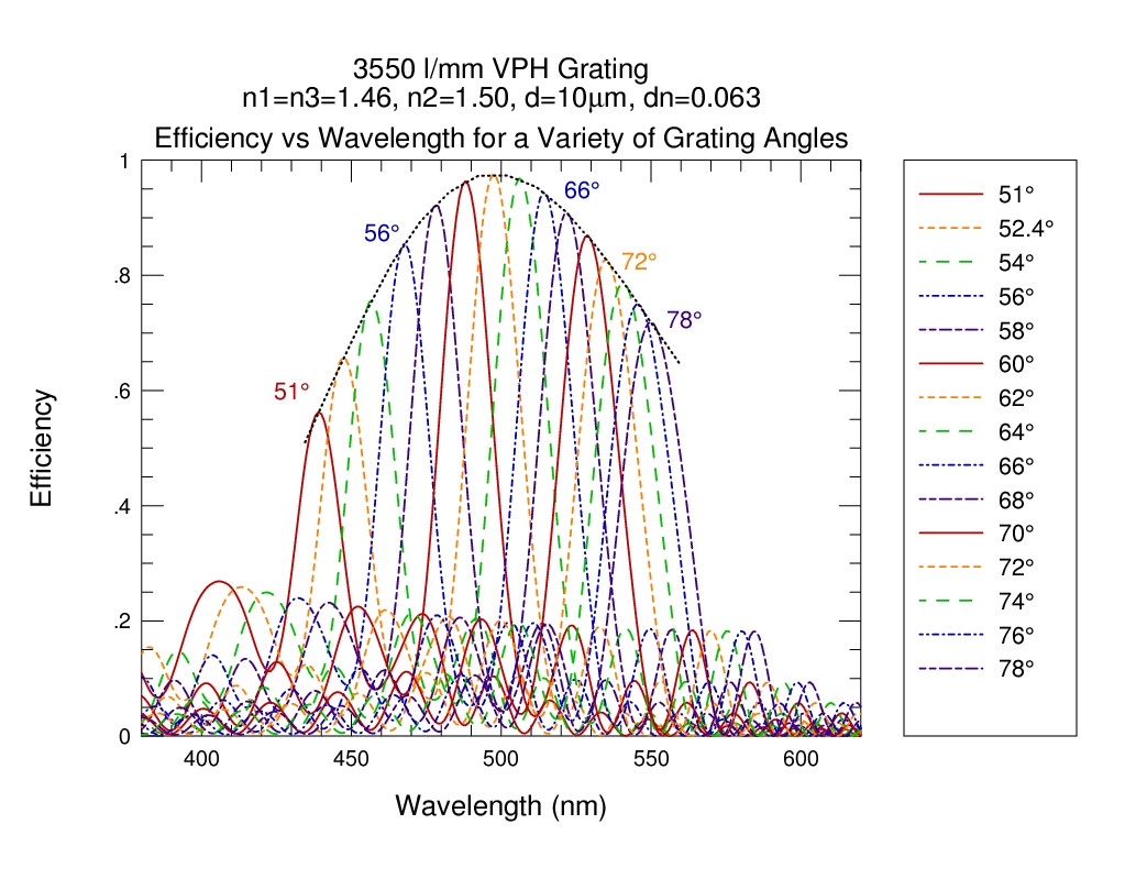
Detailed Information on Diffraction Efficiency: Below are RCWA
predicted 1st-order grating diffraction efficiencies for the three
pairs of values of gelatin thickness and index modulation, assuming n1
= n2 = 1.462 and n3 = 1.5: d = (6, 8, 10) microns, dn = (0.10, 0.078,
0.063), and dlogn = (0.042, 0.052, 0.067). These values are what CSL
has settled on for the WP4200 grating, with their current goal to
obtain d = 6 microns and dn = 0.1 (dlogn = 0.0667). What is
currently shown are efficiency plots of incidence angle (alpha) vs
wavelength in BW and color, as well as color line plots of efficiency
vs wavelength for a series of angles. As before, these plots do
not include reflection losses.
| d = 6 microns dn = 0.100 n1=n2=1.462, n3=1.50 |
d = 8 microns dn = 0.078 n1=n2=1.462, n3=1.50 |
d = 10 microns dn = 0.063 n1=n2=1.462, n3=1.50 |
|
| Efficiency Maps: incidence angle vs wavelength (BW version) |
 |
 |
 |
| Efficiency Maps: incidence angle vs wavelength (color version) |
 |
 |
 |
| Efficiency Maps: incidence angle vs wavelength (color version) |
 |
 |
 |
For comparison:
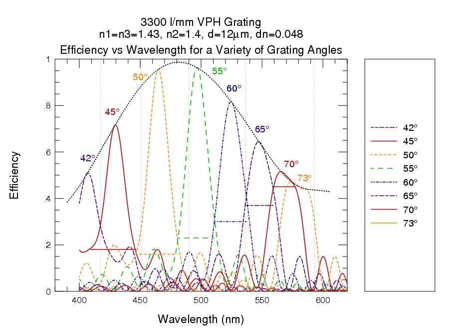
| These are RCWA predicted grating diffraction efficiency in first order for a 3300 l/mm VPH grating with unknown parameters (Barden). Our design for the 3550 grating has shifted the superblaze from about 62.5 deg and 525 nm seen in this figures to the proposed values of 65 deg and 511 nm. | 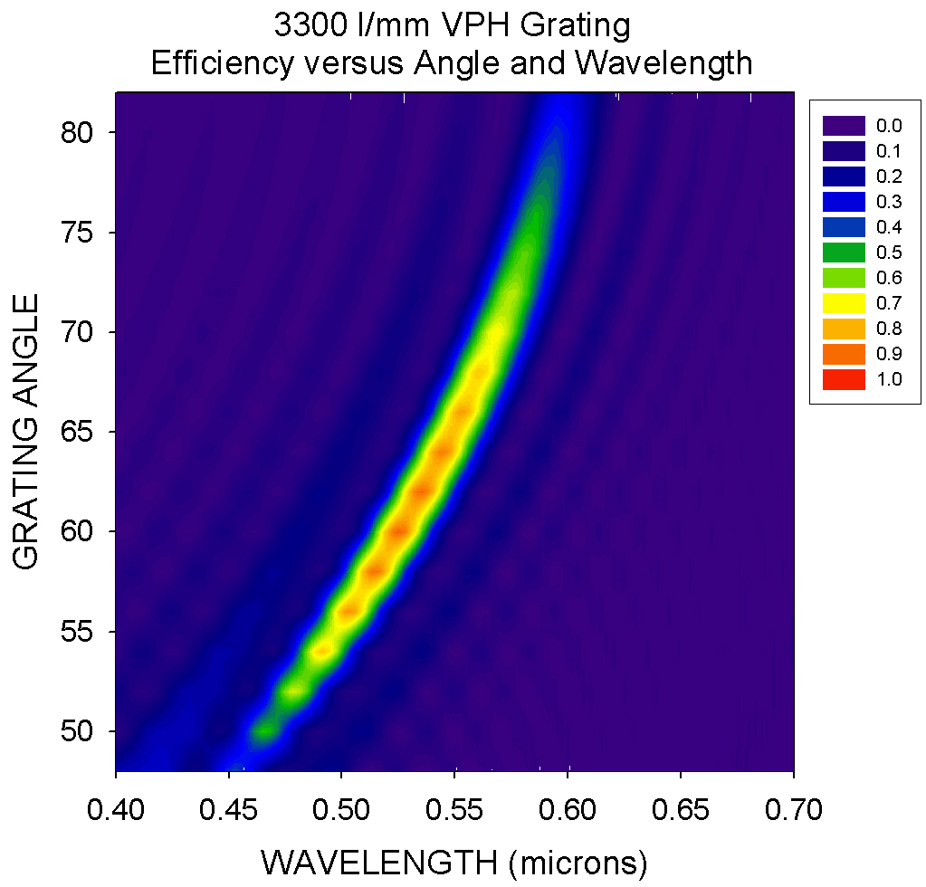 |
 |
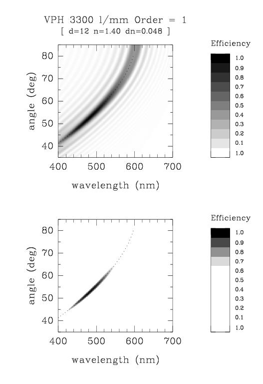
These are the RCWA predicted efficiency of 3300 l/mm VPH grating
WP3200 parameters from CSL (Bershady estimates):
|
 |
 |
![]() Efficiency measurements at CSL in a small (1 cm) beam indicate
peak diffraction efficiencies at 510 nm, corresponding to an incidence angle
of rougly 57.25 deg. Note that in the Figure here (left), an attempt
has been made to correct the measured transmissivity (transmission efficiency)
for surface (reflection) losses.
Diffraction efficiency is expected to be "1 - transmission efficiency."
Efficiency measurements at CSL in a small (1 cm) beam indicate
peak diffraction efficiencies at 510 nm, corresponding to an incidence angle
of rougly 57.25 deg. Note that in the Figure here (left), an attempt
has been made to correct the measured transmissivity (transmission efficiency)
for surface (reflection) losses.
Diffraction efficiency is expected to be "1 - transmission efficiency."
This is a combined measurement of the corrected TE and TM polarizations. The absolute calibration of this diagram is TBD. Laser-line measurements in both polarizations indicate a somewhat higher diffraction efficiency. (A detailed exchange between MAB and PAB at CSL is in an email record.) Measurements at CSL in various grating locations indicate some non-uniformities in the diffraction efficiency over the grating. In general, the center of the grating appears to perform best.
The measured >70% peak diffraction efficiency in this plot corresponds to incidence angles alpha between 50 and 65 degrees or central waves of 465 nm and 545 nm. The >80% peak diffraction efficiency is expected between alpha of 53 and 60 degrees or 485 nm and 525 nm.
The initial step is to determine how to place this holder into the primary (1st) grating turret so that the beam is un-obstructed and the grating is well-aligned. A phone-message report from Di to Pat (05 Apr 06) indicates Di and Gene have a plan and some ideas on how to accomplish this.
The primary goals of the grating testing are to explore the image quality and throughput of the VPH grating. Overall during the tests:
The detailed procedure must take into account the fact that the current camera mount constrains setups to camera-collimator (&thetacc) angles smaller than 70 degrees (see this email from Di). This means we are restricted to testing grating incidence angles &alpha = (180-70)/2 = 55 deg, which corresponds to cwl of 496.5 nm or larger. This means we can match the central wavelengths of the following VPH and echelle setups as per this table:
| WP4200: 3300 l/mm VPH | echelle |
| cwl = 513.1 nm | cwl = 513.1 nm |
| &alpha = 57.85 deg | &alpha = 68.99 deg |
| &thetacc = 64.3 deg | &thetacc = 11 deg |
| order 1 | order 11 (10.96) |
| no filter | X14 filter |
| optimize camera back-distance to minimize vignetting seperately in both cases | |
The specific test-measurements for this April 2006 T&E, in order of priority:
If it is possible, create two grating masks that (1) maks-off the elliptical area of the inner region of roughly 150-160 mm diameter in the slit dimension (appropriately elongated in the dispersion dimension for the grating inclination), and (2) mask off the annular area outside the 150-160 mm diameter.
Choose the one setup (&alpha) appropriate for the elliptical masks (I would recommend 55-60 deg), and take line-lamp and dome-flat exposures in a sequence starting with no mask, mask-1, mask-2, and then no mask again.
| wavelength range on current CCD | ||||
| &alpha | cwl | blue limit | red limit | Comments |
| (deg) | (nm) | (nm) | (nm) | |
| 55 | 496.5 | 480.5 | 510.6 | |
| 57.85 | 513.1 | setup for comparing to echelle | ||
| 60 | 524.9 | 510.8 | 537.0 | |
| 65 | 549.3 | 537.2 | 559.3 | |
| 70 | 569.5 | 559.5 | 577.4 | |
As always: Comments and discussion more than welcome. If we need to depart from this plan I'd like to hear about it in advance.
-MAB, 09 Apr 06
| |
|
|
|
|