WIYN Instrumentation:
Bench Spectrograph Upgrade
|
WIYN Instrumentation: |
|
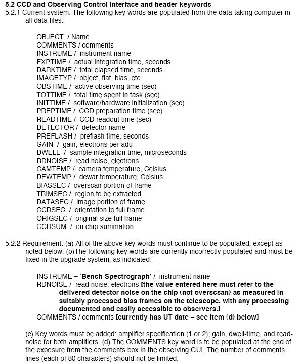
|
Project Team
M. Bershady - Project Scientist
Consultants: S. Barden, D. Harmer, C. Harmer,
|
Contents | |||
| Overview | Collimator | Spectrograph Layout | |||
| Schedule | VPH Gratings | Throughput Budget | |||
| Simulator | CCD | Beam Profile | |||
|
(password protected) |
|||||
Links to related sites:
| |||||
|
This project is funded by the WIYN Consortium. Figures and documents on this and related web pages may not be reproduced or published without permission of the Project Team. |
These project will commission and document all of the new subsystems, and provide software for scientists to explore and optimize different spectrograph configurations.
A working proto-type of this configuration tool is available. This GUI can be used to optimize setups and calculate exposures for all gratings and fiber cables (calibrated with measured system throughput values where available; see Simulator). Modification of the camera-collimator angle (for conventional gratings) can optimize blaze-wavelength and anamorphic factors.
A more complete description can be found in our Sept 2003 report to the WIYN SAC and Board, which serves as our Concept Design, in the links above, and in the project schedule and status.
| Collimator | VPH Capabilities | VPH Gratings | CCD and controller | Team working page (password protected) |
Collimator
A low-density grating capability has been designed and implemented.
A large fold-flat with a good Al coating has a
mount for the first grating
turret. A mount, turret, and appropriate "bar" (link between first and second
turret) have been fabricated and tested at fold angles of 22.5 degrees
(full fold of 45 degrees). Some work remains on improving
the optomechanics and metrology of these components, as well
as some annodization of components. However, the current
is now in use and available to the community for general application.
The most significant future development includes
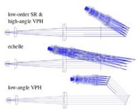
VPH Transmission Grating Capability
VPH Transmission Gratings
The combination of these changes will ensure that VPH gratings
can be used at all incidence angles on the upgraded Bench Spectrograph.
|
| Optical Design | Team
working page (password protected) |
Optomechanics | Team working page (password protected) |
The design is heavily constrained by the project-level requirement to
keep the existing camera. The initial design consisted of a 3-element
corrector with tilted elements (akin to the Wynne triplet, but using
tilted, full spherical segments). A preliminary tolerance analysis
showed the Bench implementation was likely unbuildable. The current
off-axis design has 4 corrector elements and yields improved image
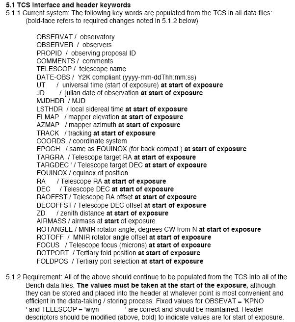
performance than the existing on-axis design. Other considerations
included:
Optical Design
Optomechanical Design
| Team working page (password protected) |
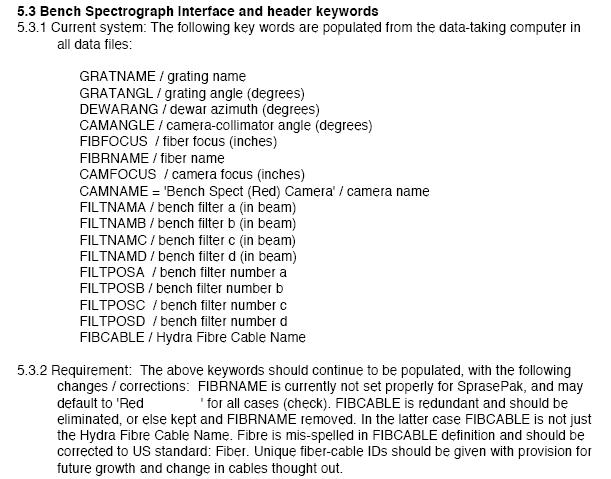
Spectrograph Geometry: Detailed notes on optical element size and location, as well as obstructions. This is used for determining both the required layout of the upgrade Bench, as well as the throughput budget.
|
The VPH grating development for the Bench was initiated by Barden (see, for example Barden et al. 2000, PASP, 112, 809) as part of a more general NOAO effort in advanced instrumentation. The advantage of VPH gratings relative to conventional surface-relief gratings is their high throughput (up to 90%), large super-blaze (i.e., good efficiency over a broad range of tunable central wavelengths), low scattered light, and transmisivity instead of reflectivity. The latter permits more compact spectrograph designs, particularly for large incidence-angle (i.e., high dispesion) setups, which allows for more optimum pupil placement, and hence less vignetting.

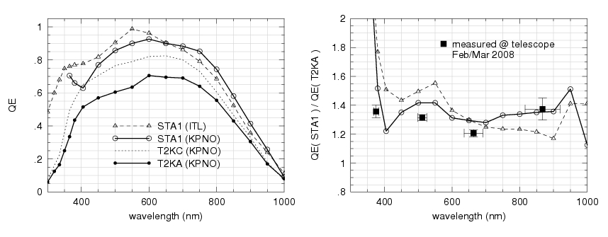
 The existing surface-relief grating suite for the WIYN Bench
Spectrograph delivers a wide range of coverage in wavelength and
resolution, as shown here in the left-hand figure. A completed Bench
upgrade may include a set of VPH gratings which replace or augment the
current capabilities of the existing gratings in this plane. Some
examples of possible VPH grating suites are shown in the
right-hand figure.
The existing surface-relief grating suite for the WIYN Bench
Spectrograph delivers a wide range of coverage in wavelength and
resolution, as shown here in the left-hand figure. A completed Bench
upgrade may include a set of VPH gratings which replace or augment the
current capabilities of the existing gratings in this plane. Some
examples of possible VPH grating suites are shown in the
right-hand figure.
Two gratings resulting from the initial VPH effort, as contracted to Centre Spatial de Liege (CSL), will be part of the initial Bench Spectrograph upgrade: 740 l/mm and 3550 l/mm gratings. These are shown as red curves in the above, left figure. At this time, testing is underway on the 740 l/mm grating. The development is mature enough to offer the grating in Shared Risk mode for 2005B. We have taken delivery of a test-version of a small high-line-density grating (3300 l/mm). This was made on float glass and is not science grade. The high-density (3550 l/mm) science-grade vph grating is still under manufacture as of April 2005.
Grating Pages:
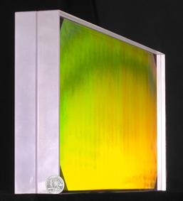
| Grating Substrate | ||||||||||||||||
| DCG parameters | physical aperture | clear aperture | ||||||||||||||
| Grating Name | l/mm | (um) | dn | n=n2 | phi |
height (mm) | width (mm) | depth (mm) |
height (mm) | width (mm) | substrate
material | index n1=n3 |
grating man. | post-polish | coating | mount |
| v740a | 740 | 17 14 effective | 0.03 | 1.43 | 0 | 220 219.46 |
240 239.55 |
24 24.55 |
200 | 211.5 | Diamant float glass; 2x12mm thick | ? | CSL | Yes; 2D Strehl of 0.7, 0th-order transmission; 2D Strehl of 0.1 for -1 order; LLNL | Yes; soft MgF2; KPNO | completed; KPNO |
| v3300a CSL/WP3200 | 3300 | 12 | 0.048 | 1.43 | 0 | 120 | 170 | 24 | 100 | 150 | Diamant float glass; 2x12mm thick | ? | CSL | TBD | TBD | TBD |
| v3550a CSL/WP4200 | 3550 | 6 pending | 0.10
pending | 1.5 pending | 0 | 230 | 500 | 30 | 210 | 480 | Zygo FS 7980 2F |
1.462 at 20 C and 1 atmos. | CSL | No | Yes; TBD | TBD |
Notes-
|
One ramification of this upgrade is that with a flat detector, the
last camera element will be changed. The
opportunity will be taken to re-coat the camera element to improve red and blue
response and at the same time decrease scattering.
WARM images taken with eight of these are shown below. Note the left
side of w10 and w11 are confused, and may be the same half-device -
the bad column is exactly in the same place on both.
These are all warm, relatively high illumination images - some things
get better cold and others get worse.
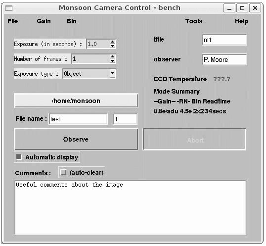
Controller: MONSOON
Parameter summary [Detailed information provided in links]
CCD Subsystem: Design Requirements
version 2 - working document reviewed by WIYN SAC
version 3 - final project document CCD Subsystem: Early Results
Lot 1 foundry run
As of September 2004, a successful foundry run at Lincoln Labs for OTA
CCDs has also produced 10 very promising, standard devices for the
Bench. These are 2600x4000 12 micron pixel devices. Three to four of
them have a single hot or blocked column. Five of these are now at
Mike Lesser's lab for cold testing. w01
w01
 w03
w03
 w04
w04
 w05
w05
 w07
w07
 w09
w09
 w10
w10
 w11
w11
Lot 2 foundry run
This URL shows images of
each of the 12 CCDs in Lot 2. Each is labeled as wN.gif, where N is the wafer
number. Wafers 9-12 are made with the high resistivity material that allows for
better red response.
Also see George's notes from the report on CCDs for the last telecon (pre 19
Dec 2005).
Surface flatness for one device
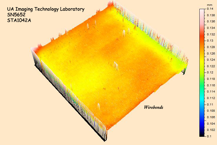
This detector (SN 5652) is flat over the great majority of its imaging area to
+/- 5 microns, and is typical of the devices from Lot 2, and the device (5644)
ultimately adopted for the Bench system.
CCD Subsystem : Delivered Performance
: FITS
High 0.21 e-/DN
Medium 0.44 e-/DN
Low 0.87 e-/DN
Gain/Binning:
1x1
2x1
2x2
4x2
4x3
High
227
131
67
43
29
Medium
140
87
45
31
22
Low
97
65
34
25
18
Detector
Gain/Binning:
Overscan
1x1
2x1
2x2
4x2
4x3
High
3.4
3.7
4.0
4.1
4.4
Medium
3.8
4.3
4.4
Low
5.5
5.9
| ↑ Top | ← Research | ← Home | → WIYN Home Page |