 SparsePak IFU / Description
  SparsePak IFU / Description
 |
SparsePak o General o User o Technical |
Related Information o WIYN Home Page o Bench Spectrograph o DensePak |
 SparsePak is a new fiber-optic bundle built for the WIYN telescope's
Bench
Spectrograph, successfully installed and tested on WIYN in May
2001. Such bundles are often referred to a "integral field units," or
IFUs. This bundle is a "formatted field unit," with a special fiber
geometry designed to optimize performance for specific science goals:
the study of the spatial distribution of the internal motions of gas
and stars in nearby galaxies. SparsePak should also be useful in
general for the study of galactic and extra-galactic nebulae (e.g.,
planetary nebulae, star-forming regions), and comets. SparsePak's
large fibers may make it feasible to use this array for
spectrophotometry.
SparsePak is a new fiber-optic bundle built for the WIYN telescope's
Bench
Spectrograph, successfully installed and tested on WIYN in May
2001. Such bundles are often referred to a "integral field units," or
IFUs. This bundle is a "formatted field unit," with a special fiber
geometry designed to optimize performance for specific science goals:
the study of the spatial distribution of the internal motions of gas
and stars in nearby galaxies. SparsePak should also be useful in
general for the study of galactic and extra-galactic nebulae (e.g.,
planetary nebulae, star-forming regions), and comets. SparsePak's
large fibers may make it feasible to use this array for
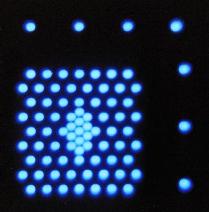
spectrophotometry.SparsePak has 82 active fibers. These are arranged in a sparsely packed grid, with a small, nearly-integral core. Seven 7 sky fibers are spaced away from, but on two of the four sides of the grid. Why this shape? Check out this simulation of SparsePak overlayed on an unsuspecting target.
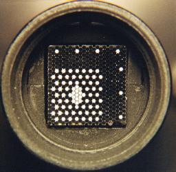
To the upper-left is a digitized photograph of the SparsePak fiber head enclosed within its mount. The entire array has a size of 0.46 inches on a side, which maps into a size on the sky of roughly 1/15th the diameter of the full moon. The bright fibers in this image are active, i.e., they carry light between the telescope and spectrograph. They are bright in this image because they have been back-illuminated (at the slit end). Dark fibers are short fibers (rougly 1.5 inches) used for mechanical packing. The dark circular structure around the array is a 1 inch-diameter head mounts which inserts into the imaging port of the telescope. The interior of the mount is bevelled, sand-blasted and painted with special black "flocking" paint to minimize scattered light entering the fibers from sources off the array.
The active fibers transmit light from the focal plane of the telecope down to a spectrograph housed in a climate-controlled room on the ground-floor of the telescope building. The fibers are routed down the middle of the telescope pier in a very "beefy" but flexible steel cable. This cable has a large enough minimum-bend radius to prevent "stressing" the glass fibers. At the spectrograph input, the fibers are re-arranged into a long (3 inch) slit. The spectrograph produces a spectrum of each fiber, which is recorded by a CCD. The digital spectra can then be re-formated on the computer to form spectral images of whatever source(s) fall on the fiber array.
User-level Instrument Description
SparsePak currently mounts on WIYN's Nasmyth Imaging Port (IAS), into
WIFOE, just as does
Densepak. As such, SparsePak is operated in a manner essentially
identical to Densepak, including acquisition of dome flats, comparison
lamps and focal plan viewing with the back-illuminator. Likewise,
basic data reduction can be accomplished via dohydra, with the
same caveats concerning using complicated, black-box software.
Each of SparsePak's 82 fibers has a physical size of 500 microns. This maps to 4.687 arcsec at the WIYN/IAS port. The sparsely packed grid has dimensions of order 72x71.3 arcsec. There are 7 sky fibers (part of the 82 total fibers) placed another ~25 arcsec away from the grid. Here is a detailed map of the theoretical SparsePak on-sky geometry. The actual geometry is very close to this map, which is based on lab images and micrometer measurements of the SparsePak face. An astrometric table is available here. A second table at this link provides offset patterns for filling the array and sub-sampling the densely packed core.
Sparsepak fibers are "very red." Fiber transmission begins to drop sharply blueward of 500 nm. Initial estimates are that the fibers are transmitting 89-92% of the light longwards of 500 nm (theoretical best-case is 92%). Hence the cable is very efficient for work between rest-frame MgIb and the CaII NIR triplet. A summary of the instrument performance can be found at this link as well as in the two SparsePak papers listed below. We have developed several setups with the echelle in the 515nm, 660nm and 860nm regions, capable of achieving spectral resolutions between 9000 and 21,000. The details of these setups are found under ``Observing Information".
There are two minor differences between DensePak and SparsePak operations and reductions:
1. The fiducial rotation of the IAS which places the sky fibers due N and W of the array appears to have changed between our two runs to date by 6.5 degrees. Since SparsePak is locked into the WIFOE via two detents, it appears unlikely this is due to a change in the SparsePak mounting. At this time we recommend users check the alignment with the focal plane viewing camera and a drifted star. Expect good alignment for IAS PA's of +/-10 degrees from the home (zero) position.
2. The mapping of fibers between telescope and spectrograph focal planes in non-trivial for SparsePak. The reasons for this are historic as well as an attempt (a) to put central fibers in the telescope focal plan towards the edge of the slit where vignetting is largest, and (b) to intersperse sky fibers all along the slit. Here is the SparsePak telescope focal-plane to slit mapping. A script is available from this site for "re-packing" dohydra output into a more "viewable"" format.
For data reduction, here is the ".iraf" file for dohydra.
SparsePak: A Formatted Fiber Field-Unit for The WIYN Telescope
Bench Spectrograph. II. On-Sky Performance, Bershady, M. A.,
Andersen, D. R., Verheijen, M. A. W., Westfall, K. B., Crawford,
S. M., Swaters, R. A. 2005, ApJS, 156, 311
(reprint: [local pdf]
[ApJS])
Mounts - design geometries and hardware dictated to
a large extent by existing mounting surfaces at telescope (head) and
spectrograph (foot).
Technical Instrument Description
A full description of design, manufacture and performance can be found in
these two refereed papers:
Basic hardware parameters:
Basic performance parameters: (as measured in lab)
The Cable consists of an outer sheath of heavy-gauge flexible
stainless steel conduit and an inner PVC cable jointed every 6 feet to
provide natural spacing within the larger stainles conduit. Within
the PVC cable runs 82 black teflon tubes (each containting 1
fiber). The stainless flex conduitis jointed in three segments (25
feet each) with custom machined Al connectors secured with set screws.
The stainless flex conduit serves to protect against fiber crushing
and over-bending. The PVC provides a safe, smooth inner surface for
the teflon+fiber.
(theoretical best-case is 92% for two fused-silica--air
interfaces)
(does not include spectrograph "opacity," telecope reflectance,
and atmospheric transmission)
Polishing methods and quality See Bershady
et al. 2004
Assembly/Manufacturing process - Teflon cut, and bundled into groups with shrink-wrap and flared ends. Teflon hung in stairwell (8 stories), PVC pulled up from basement and jointed on the fly. Same for stainless conduit. See Bershady et al. 2004 for further details of attaching head and foot collar; inserting fiber; sheer clamp, AR clamp, etc.