| optical element | radius or
half-width (mm) | distance to
next element (mm) |
| fiber slit | 38.1 | 1021 |
| collimator | 117.5 | 1838.9 |
| echelle grating | spatial x spectral 103 x 203 | 1016 |
| low-order gratings | spatial x spectral 101.5 x 115 | 390 |
| camera objective (red) | 103.0 | 533.5 |
| camera objective (Simmons) | ??? | ??? |
| detector | | |
|
Distances (mm) and f/
|
| collimator focal length: | 1021 |
| collimator-grating distance: | 1838.9 |
| grating-camera distance: non-echelle | 390 @ 30 deg |
| grating-camera distance: echelle | 1016 @ 11 deg |
| camera focal length: | 533.5 (physical: objective to CCD) |
| camera objective: | 134.4 |
| fastest unvignetted, on-axis beam for camera: | f/1.98 |
|
| Known Obstructions:
-
1. Fiber Feed. This is currently on-axis,
in the beam, at the pupil.
- width (transverse to slit dimension): 12.8 mm
- height (parallel to slit dimension): +55.5 mm /
-190.7,
where the + direction is "down" towards the table, to
higher fiber numbers; and the - direction is "up" away from the table,
to lower fiber numbers.
- length (along the beam): 217 mm = 181 mm between
focus and grating (down stream) + 36 mm between focus and collimator
(up stream).
NB: Since this is a curved piece with a snout,
there is no single number which can characterize the length. However,
a number which should be representative is the axis length, which is
given. The numbers are for the original toes, i.e. blue MOS, red MOS
and DensePak; the SparsePak length is slightly shorter (up stream
length is 28.6 mm).
At this, the fiber feed obstruction is included the
Bench Simulator.
2. Fiber-Feed Mount. This is a thick, semi-circular mount
that is significantly outside of the current beam, since it is at the
pupil (as per visual inspection by D. harmer, C. Harmer and
M. Bershady, Feb 17, 2003). Because of the cable hardware on top, this
mechanical hardware will become an issue for vignetting if a
field-lens is used to push the pupil back significantly. At this time,
it does not appear that a field lens is feasible in the upgraded
system, and it is likely we will move to an off-axis collimator. Hence
this element is unlikely to be important, and currently is not
included in the Bench
Simulator.
3. Toes and Filters. The attached
figure shows the geometry for what should be the critical stops in the
toes. This analysis makes the simplifying assumption that all light
emanates from the center of the fibers. Each cable has "toes" at the
end of the fit, which is a multi-chambered extension to hold a slit
mask and up to three filters (Hydra and Densepak), or two filters
(SparsePak). The SparsePak toes are shorter. The DensePak and Hydra
toes have internal chamber apertures that widen with distance from the
slit end. The SparsePak toes have chamber that are larger, and are
constant. In the adopted, simplified model where all rays emanate from
the center of each fiber, the limiting stop turns out, in all cases,
to be the last aperture. If one considers ray-bundles exiting from
the edge of the fibers then on the Hydra and DensePak toes, the first
two chambers provide the limiting stop. The present analysis does not
take this into consideration, and the issue should perhaps be revisted
in the future if the present model does not provide an accurate
description of the observed data. At this time, the overall
vigenetting model appears to be accurate to better than 10%.
Currently, the limiting stop obscures
rays faster than f/5.7 in the perpendicular dimension and f/5.65 in
the parallel dimension (for edge fibers only) for DensePak and Hydra
cables; the limiting stop obscures rays faster than f/4.1 in the
perpendicular dimension and f/2.1 in the parallel dimension (for edge
fibers only) for SparsePak. Orientations here are w.r.t. the slit.
Measurements to define the stop from
both interference and glass order-blocking filter were completed on
Feb 17, 2003 and added to this figure in Oct
2004. We also observed that the filters, when placed at their
respective distances, did not vignette an f/5 beam output from a
thick, coherent bundle (this was done during tests with D. Harmer,
C. Harmer, and M. Bershady). This indicates the above concerns about
additional vignetting from fiber edges are likely unimportant. Direct
calculation using the numbers in this figure
shows that either the interference or glass filter placed in the first
filter slot is a more open stop than the end of either the SparsePak
or other feeds. This assumes the filters are inserted with the
filter-aperture stop facing the fiber.
Summary: Limiting stops for
this component are "S" and "O" in this
figure.
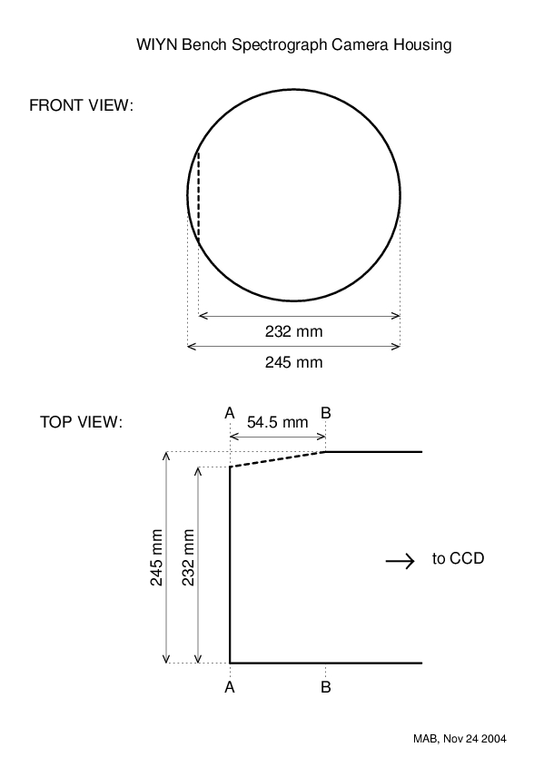
4. Camera Mount. The attached
figure shows the geometry for what should be the critical dimensions
for determining the limiting stops of the camera. The vignetting from
these elements will depend on the camera-collimator angle and the
back-distance of the camera (camera-grating distance). Depending on
the camera-collimator angle and the angle of the bevel in the front
side of the camera mount, one of two cross-sections of the camera
mount will provide the limiting stop: A-A or B-B in this figure.
This is the highest-priority
element to add to the Bench
Simulator because it will determine the optimum back distance of
the camera. This in turn will place constraints on the layout of the
upgraded Bench. The specific constraint will come from the maximum
back-distance needed to optimize configurations with the echelle with
an 11 deg. camera-collimator angle. Note that if toe/filter vignetting
is added (item 3 above), this will modify the results here since the
vignetting is in the same plane as the camera vignetting.
Final note: Order of the above in light path is: 3, 4, 1 & 2.
|